High frequency wireless pacemaker

a wireless pacemaker and high frequency technology, applied in electrotherapy, heart stimulators, therapy, etc., can solve the problems of limited data rate and limited transmitter power, and achieve the effects of low power consumption of pacemakers, reasonable range, and high frequency operation

Inactive Publication Date: 2007-10-30
CAMPBELL DAVID +1
View PDF8 Cites 229 Cited by
  • Summary
  • Abstract
  • Description
  • Claims
  • Application Information

AI Technical Summary

Benefits of technology

[0014]The present invention enables design of a wireless pacemaker and wireless communications system that is optimal for its application. Namely, high frequency operation, low pacemaker power consumption, reasonable range, high data rate, minimal RF radiation of internal pacemaker circuitry, small pacemaker antenna system, simple pacemaker RF circuit design, high reliability, low pacemaker cost, and use of existing pacemaker construction methodologies. The wireless communications system may operate in the 403 MHz band intended for medical applications, the 902 to 928 MHz ISM band or any other high frequency. The wireless circuitry in the pacemaker can be designed to consume less than 10 mA (while transmitting) and communicate with a wireless monitoring base station at a distance of at least 10 feet (although significantly greater distances are possible).

Problems solved by technology

Also, since a pacemaker is battery powered, available transmitter power is limited.
As such, near field solutions dramatically limit range, and since these solutions are also low frequency, data rates are limited.
The challenge is to develop a high frequency design that has acceptable antenna performance, while minimizing size, power consumption, and radiation of pacemaker circuitry.

Method used


Image

  • High frequency wireless pacemaker
  • High frequency wireless pacemaker
  • High frequency wireless pacemaker

Examples


first embodiment

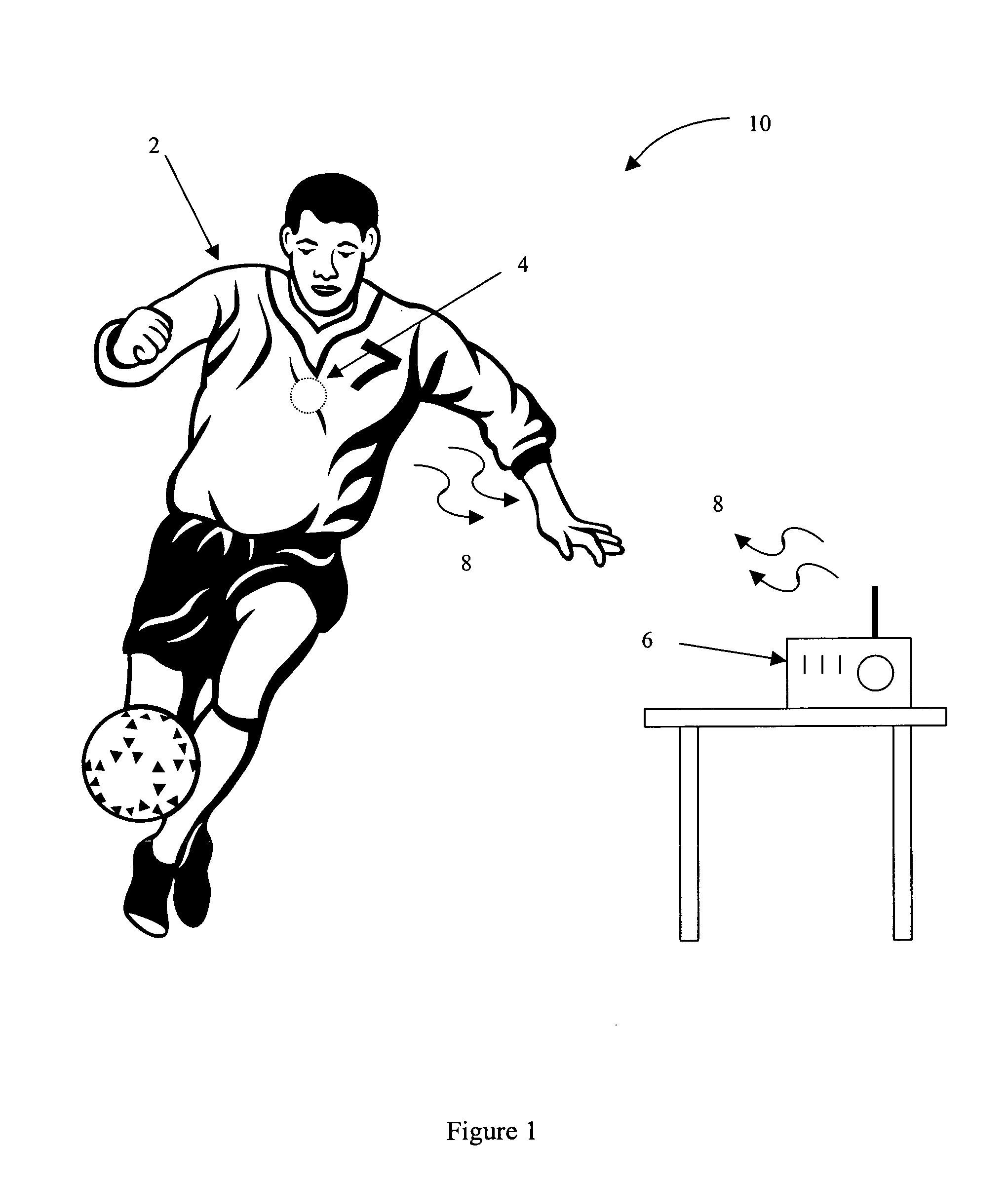
[0044]the invention is comprised of an Implanted Wireless Pacemaker 4 which has been designed to provide all conventional pacemaker functionality while providing the ability to communicate with a Wireless Monitoring Base Station 6 as part of a Wireless Communications System 10. The Implanted Wireless Pacemaker 4 can be designed for two-way communications, or can be designed to only transmit to the Wireless Monitoring Base Station 6.

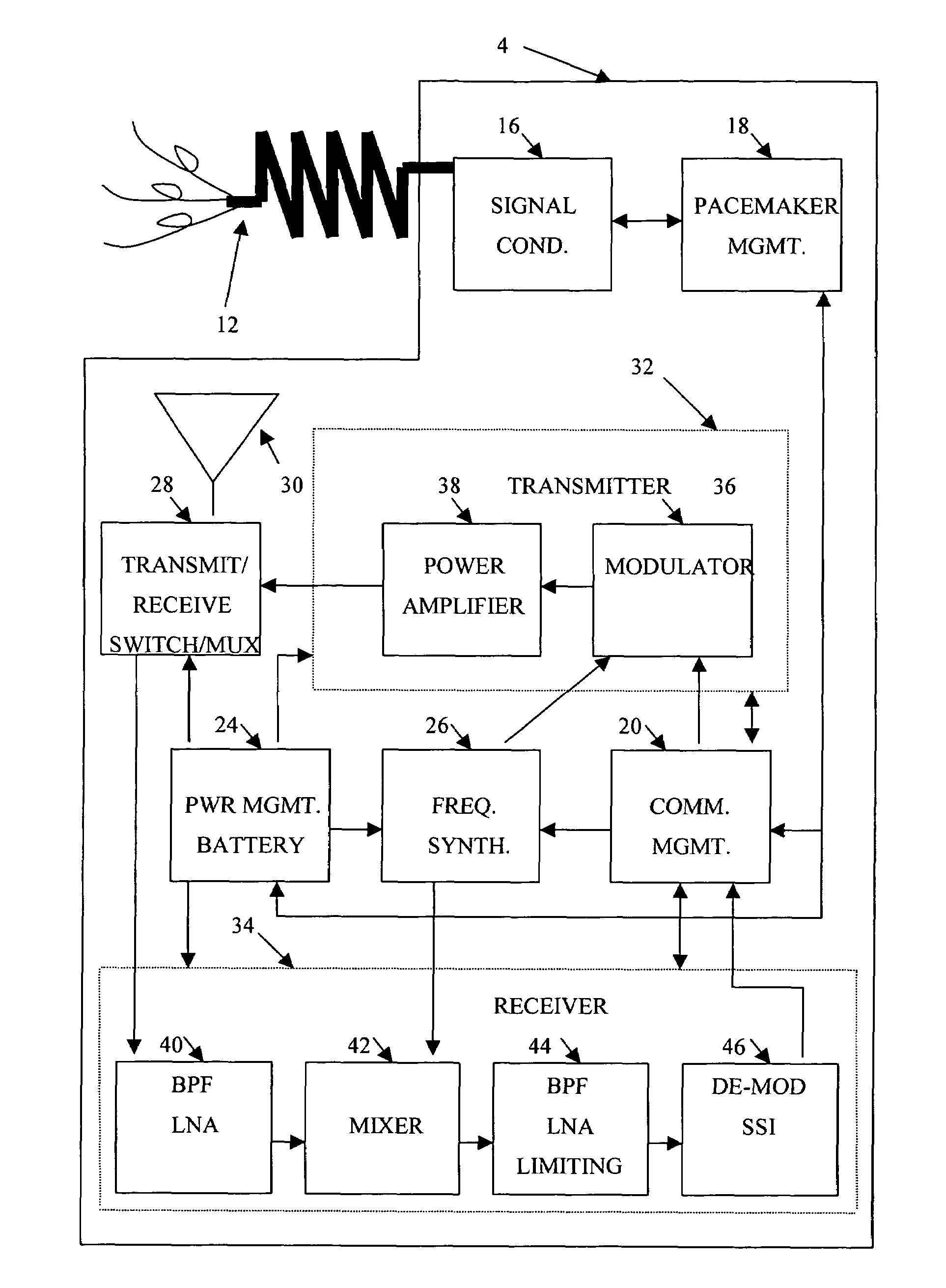
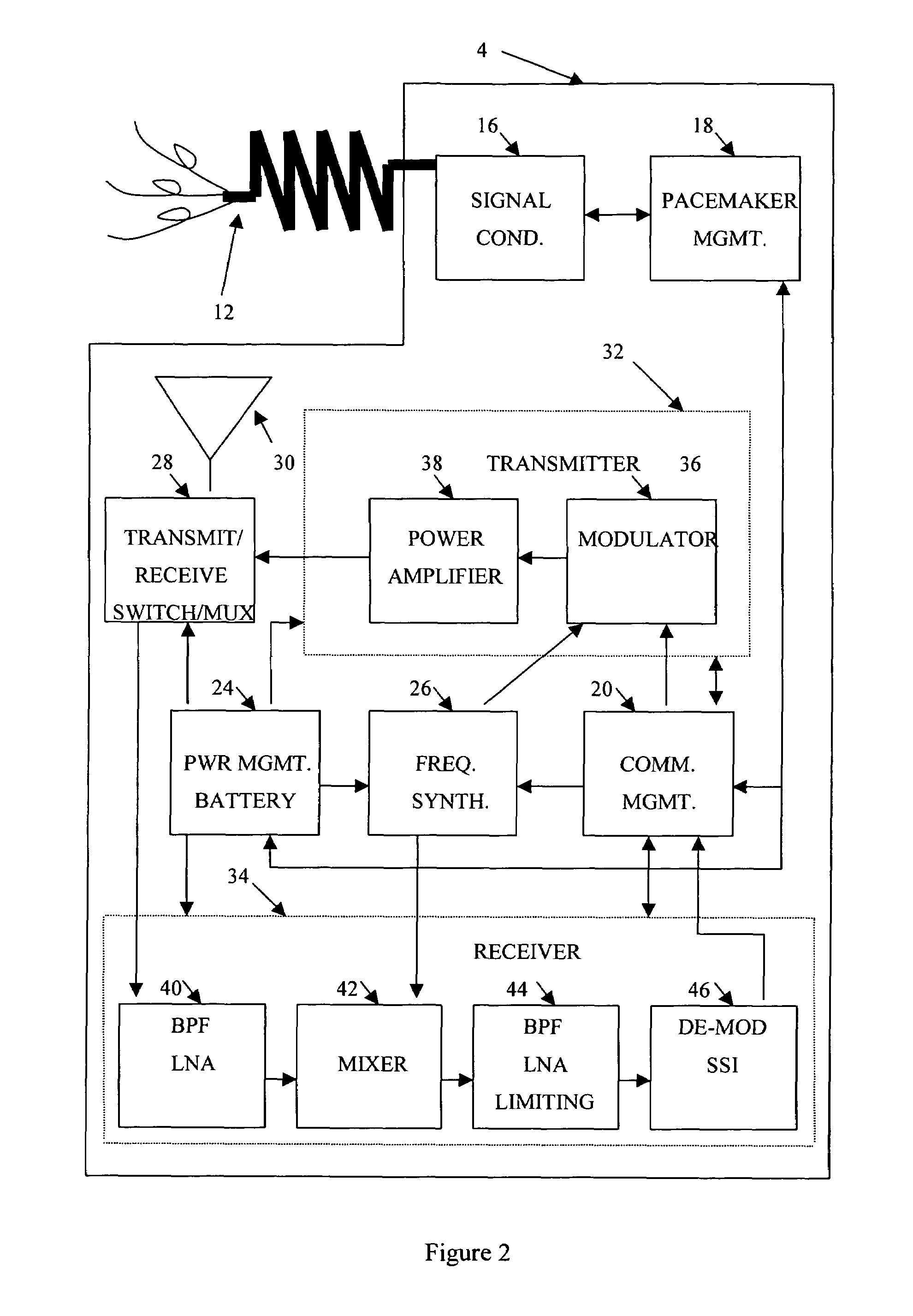
[0045]FIG. 2 illustrates the contents of a two-way, Implanted Wireless Pacemaker 4 which has been optimized for effective communications while minimizing battery power consumption. A set of Implanted Cardiac Leads for Monitoring and Pacing 12 is connected to Signal Conditioning Circuitry 16 in the Implanted Wireless Pacemaker 4 and provides the electrical connection to the patient for receiving electrical cardiac monitoring signals and for sending cardiac pacing signals to the patient (defibrillator signals could also be sent to the patient). Signal Condi...

fourth embodiment

[0063]the invention is to use the Wireless Pacemaker Housing 128 as the transmitting and / or receiving antenna. The completed Wireless Pacemaker Housing 128 is generally shaped in the form of a thick pancake. It is constructed of two halves such that one Pacemaker Housing Half 134 is designed to fit into the other Pacemaker Housing Half 134, similarly to a can of shoe polish with its lid (see FIG. 10A). When the housing is assembled, the halves are electrically insulated from each other using an insulating material 132. The electrical Insulating Material 132 is applied to both Pacemaker Housing Halves 134 to electrically isolate each Housing Half 134 from the other. The Insulating Material 132 could be comprised of a thin non-conducting film coated on each side with non-conducting adhesive to bond the film to each housing half. Alternatively, the insulating material 132 could consist of a non-conducting adhesive containing non-conducting particles (such as large plastic granules) tha...

fifth embodiment

[0066]the invention is to use the Wireless Pacemaker Housing 128 as the transmitting and / or receiving antenna. Conceptually, the completed Wireless Pacemaker Housing 128 is such that the Pacemaker Housing 128 is shaped as a cylindrical metal housing with metal ends which have been completely sealed (the Housing 128 is typically constructed of titanium) as shown in FIG. 11A. The Wireless Pacemaker Housing 128 can be completely hermetically sealed (i.e. all exposed surfaces are composed of metal, glass, or ceramic and all joints are sealed by fusion, which is localized melting of the two materials comprising the joint). Generally speaking, hermetically sealed housings provide optimum protection in an implanted environment.

[0067]Each end of the Wireless Pacemaker Housing 128 is electrically driven (from circuitry inside the housing) from a Transmitting RF Power Amplifier 156 (optimized for driving the Coaxial Cables 150 connected to the metal ends of the Wireless Pacemaker Housing 128)...


PUM


Abstract

A wireless communications system optimizes performance by dividing communications functionality between a wireless pacemaker and a wireless monitoring base station according to the design constraints imposed by the system elements. Typical design constraints include high frequency operation, low pacemaker power consumption, reasonable range, high data rate, minimal RF radiation of internal circuitry, small pacemaker antenna system, simple pacemaker RF circuit design, high reliability, low pacemaker cost, and use of existing pacemaker construction methodologies.

Description

CROSS-REFERENCE TO RELATED APPLICATIONS[0001]This application is related to U.S. provisional patent application Nos. 60 / 498,450 filed Aug. 28, 2003 entitled HIGH FREQUENCY PACEMAKER SOLUTION and 60 / 555,443 filed Mar. 23, 2004 entitled HIGH FREQUENCY PACEMAKER USING BUTTON ANTENNA, the disclosures of which are incorporated herein by reference in their entireties.BACKGROUND OF THE INVENTION[0002]Most pacemaker designs utilize a metallic housing to isolate a pacemaker's contents from the implanted environment in which it is installed. The material selected must be inert to the patient and must protect the electronic circuitry from bodily fluids. Titanium is a typical housing material. Electrical leads for pacemaker signals must be connected to the pacemaker using electrical feed-throughs that preserve the environmental integrity of the housing. Since the housing is made of metal and tends to exhibit the properties of a Faraday cage, RF communications designs between a pacemaker and rad...

Claims


Application Information

Patent Timeline
Patent Type & Authority Patents(United States)
IPC IPC(8): A61N1/362
CPCA61N1/375A61N1/37229A61N1/37512
Inventor CAMPBELL, DAVIDLUGO, MICHAEL
Owner CAMPBELL DAVID
Why Eureka
Try Eureka