Active power factor correction circuit and control method thereof

a technology of active power factor and control method, which is applied in the direction of electric variable regulation, process and machine control, instruments, etc., can solve the problems of severe electromagnetic interference (emi), high switching loss of ccm pfc circuit, so as to reduce switching loss and switching noise, and reduce the effect of higher-order harmonic distortion

Inactive Publication Date: 2007-11-13
GREEN MARK TECH
View PDF4 Cites 130 Cited by
  • Summary
  • Abstract
  • Description
  • Claims
  • Application Information

AI Technical Summary

Benefits of technology

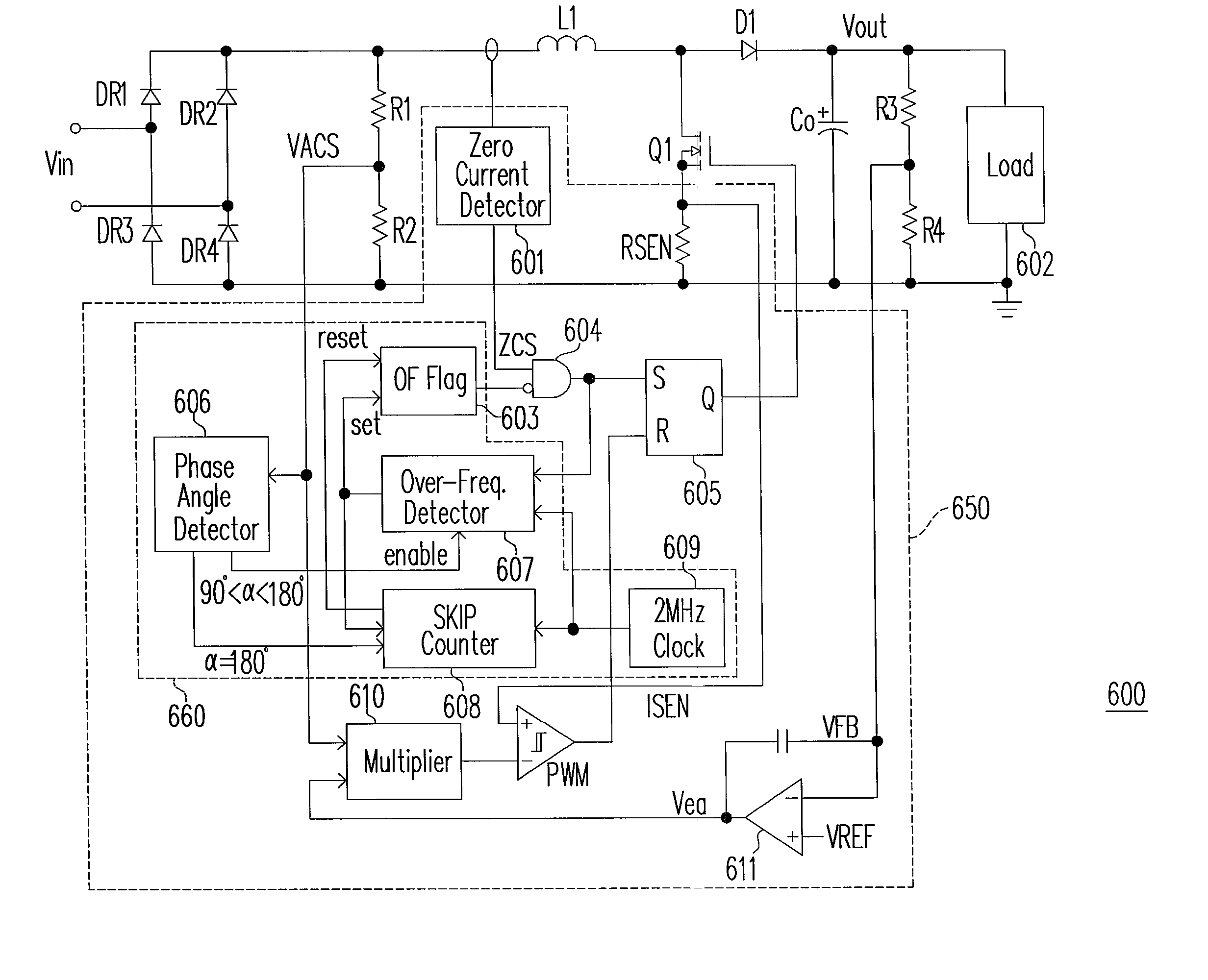
[0015]Accordingly, the present invention is directed to an active PFC circuit and a corresponding method for controlling its power switch. This active PFC circuit is an improvement over a conventional CRM PFC circuit. It retains the advantages of no diode reverse recovery loss, and low higher-order harmonic distortion. In addi

Problems solved by technology

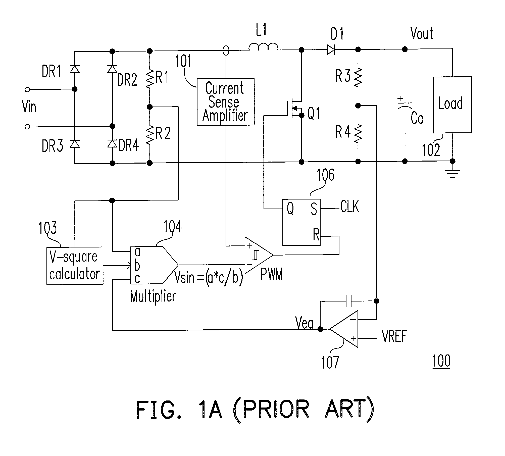
Nevertheless, a CCM PFC circuit suffers from high switching loss due to the slow reverse recovery of the output rectifier diode.
Further, a CCM PFC circuit has significant switching loss associated with the output capacitance of the power MOSFET.
In addition, the reverse recovery of the output diode and the turn-on of the power MOSFET at a high drain-to-source voltage level often lead to severe electromagnetic interference (EMI) issues.
Another issue of DCM PFC is higher order (third order and

Method used


Image

  • Active power factor correction circuit and control method thereof
  • Active power factor correction circuit and control method thereof
  • Active power factor correction circuit and control method thereof

Examples


Embodiment Construction

[0029]Reference will now be made in detail to the present preferred embodiments of the invention, examples of which are illustrated in the accompanying drawings. Wherever possible, the same reference numbers are used in the drawings and the description to refer to the same or like parts.

[0030]FIGS. 3A and 3B are schematic diagrams showing switching frequency ranges of typical CRM PFC circuits at different load conditions. FIG. 3A depicts the switching frequency ranges when the AC line input voltage Vin is 120V. FIG. 3B depicts the switching frequency ranges when the AC line input voltage Vin is 220V. There are two curves in each of FIGS. 3A and 3B. The lower curve shows the minimum switching frequency at different load conditions, while the upper curve shows the maximum switching frequency at different load conditions.

[0031]As shown in FIGS. 3A and 3B, the main drawback of conventional CRM PFC is that switching frequency can get very high, especially at light load and high line volt...


PUM


Abstract

An active power factor correction (PFC) circuit and its controlling method are provided. The method comprises the following steps. Drive the power switch of the circuit so that the average inductor current waveform follows the rectified input voltage waveform. Suspend the operation of the power switch at a first moment in a first line cycle of the rectified input voltage and then resume the operation of the power switch at a second moment in a second line cycle of the rectified input voltage. The first moment is when the phase angle of the rectified input voltage exceeds a predetermined angle and the switching frequency of the power switch exceeds a predetermined frequency. The time span from the first moment to the end of the first line cycle is substantially as long as the time span from the beginning of the second line cycle to the second moment.

Description

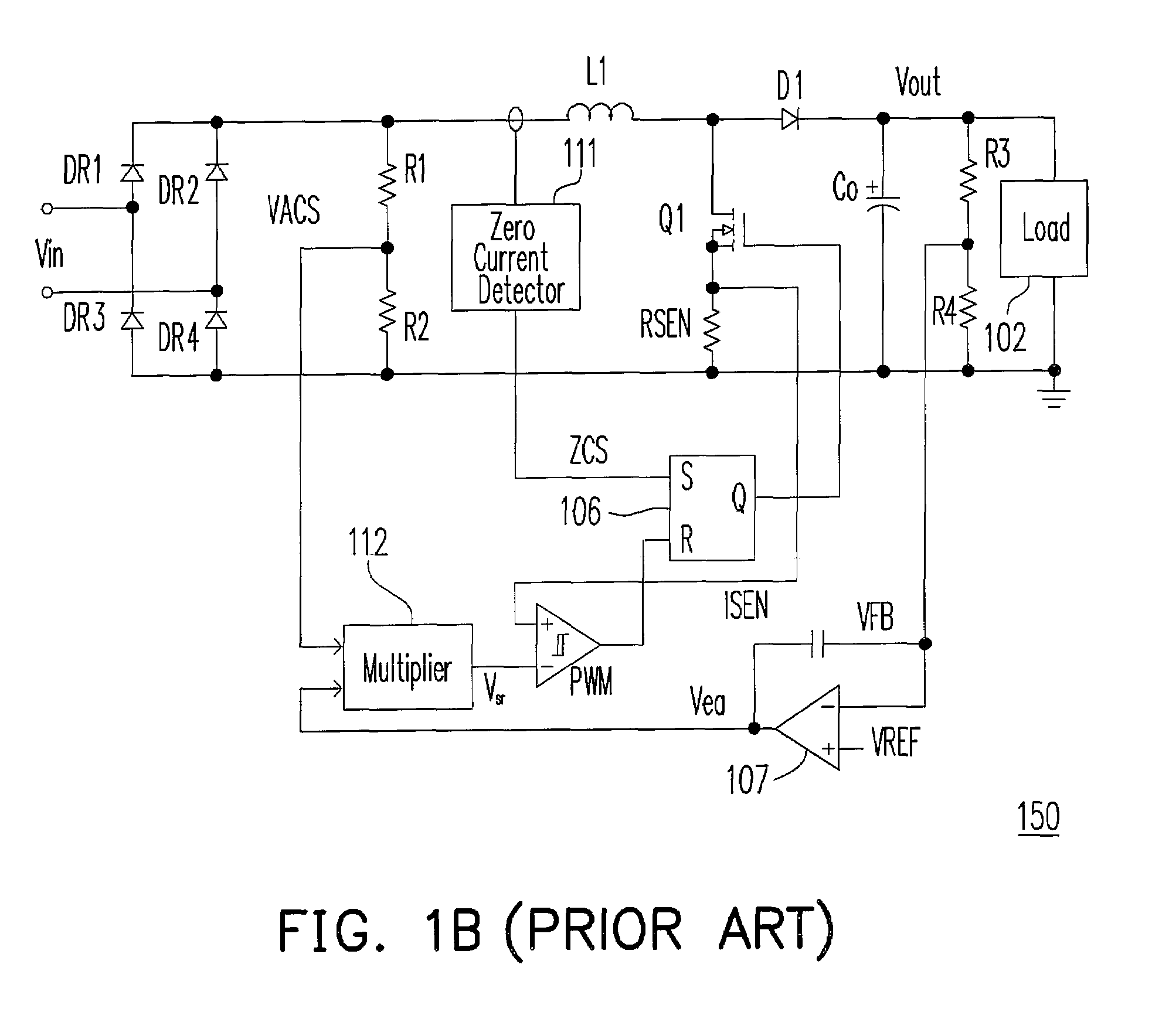
BACKGROUND OF THE INVENTION[0001]1. Field of the Invention[0002]The present invention relates to active power factor correction (PFC). More particularly, the present invention relates to critical mode (CRM) active power factor correction.[0003]2. Description of the Related Art[0004]Most active PFC circuits are based on a boost converter topology. Its main power switch is typically a high-voltage power metal oxide semiconductor field effect transistor (MOSFET) operating at high switching frequency (normally higher than the audible frequency limit of 20 kHz) such that the circuit size can be reduced. There are three major types of active PFC circuits. The first type is continuous current mode (CCM) PFC. The second type is discontinuous current mode (DCM) PFC. The third type is critical mode (CRM) PFC.[0005]FIG. 1A is a schematic diagram showing a conventional CCM PFC circuit 100. Circuit 100 comprises a bridge rectifier DR1-DR4 to rectify the alternating current (AC) line input voltag...

Claims


Application Information

Patent Timeline
IPC IPC(8): H02M5/42G05F1/10
CPCG05F1/70H02M1/4225Y02B70/126Y02B70/10Y02P80/10
Inventor LIU, KWANG-HWA
Owner GREEN MARK TECH
Why Eureka
Try Eureka