Chip microphone and method of making same

a technology of chip microphones and microphones, applied in the direction of microphone structural association, semiconductor electrostatic transducer, transducer types, etc., can solve the problems of reducing the size of the chip, affecting the design of the chip, so as to reduce the defect of the oxide film and increase the latitude of design.

Inactive Publication Date: 2007-11-20
NIPPON HOSO KYOKAI
View PDF5 Cites 22 Cited by
  • Summary
  • Abstract
  • Description
  • Claims
  • Application Information

AI Technical Summary

Benefits of technology

[0014]The chip microphone as described above can be produced as a small, highly reliable device by use of a micro-machine process technology which utilizes the semiconductor manufacturing technology. When the diaphragm and the back plate are made of silicon-based materials, the chip microphone will exhibit strong heat-resistant characteristics, allowing the use of a process. The microphone can withstand repeated exposures to the heat of reflowing or the like at the time of implementation on a circuit board or implementation as a module. Without the assembly of several parts, the present invention can produce a chip microphone having small area size and a thickness of less than 1 mm, and can implement all circuit components at once on the circuit board by use of an implementation process such as the bump / reflow process. The device for inputting sound information formed in this manner does not limit a temperature range in which the apparatus is used. Even if aluminum, which is typically used, is employed as an electrode material, the chip microphone will exhibit heat-resistant characteristics up to 300 degrees Celsius. The heat-resistant characteristics of this degree can withstand an implementation process using lead-free solder. Preferably, the electrode material is such a material as exhibiting a proper ohmic contact with substrate materials such as silicon.
[0016]In the sound processing apparatus as described above, the vibration of the diaphragm in the microphone can be detected as changes in the capacitance by applying a small voltage to the LC oscillation circuit, rather than by applying a bias voltage as in conventional microphones. The microphone and the LC oscillation circuit can be formed in the same substrate. With this provision, the present invention can avoid the diaphragm and the back plate being stuck together due to the applied voltage even if the support block is formed to have a thickness as thin as 1 micrometer to 20 micrometers. This further contributes to the size reduction.
[0018]In the sound processing apparatus as described above, the outputs of the chip microphones are added together based on the assumption that they are in phase, thereby making it possible to provide a sound input unit that is small and has low-noise characteristics. Production of the sound processing apparatus as a unit makes it possible to achieve steady characteristics of the chip microphones, small product variation, thereby providing a highly-accurate small-size audio input unit.
[0020]In the method as described above, the two substrates are bonded together after depositing the bonding layer on the bonding surface of the diaphragm substrate or the bonding surface of the back-plate substrate. Through application of a heat process, for example, the present invention bonds the substrates together with steady bonding over the entire surface, while simultaneously providing an insulating layer having a desired thickness between the two substrates. The bonding layer may contain soot silicon oxide as a main component, thereby making it possible to eliminate defects of the oxide film through sufficient infusion of an oxide substance, to bond the substrates without particular needs for the flatness of bonding surfaces and the rigorous control of cleanliness, and to increase latitude in designing the thickness of each of the substrates and the insulating layer compared to the use of direct bonding or the conventional SOI (silicon-on-insulator) technology.

Problems solved by technology

Such conventional microphones are manufactured by assembling a plurality of different components, thereby resulting in drawbacks as follows.
Because of the limitations of preciseness during an assembly process, there is an inevitable limit to size reduction.
This hinders an effort toward increasing the circuit density of circuit boards.
Since the used materials differ from component to component, and thus have different thermal expansion coefficients, distortion may occur due to heat applied during a heat process (more than 200 degrees Celsius) such as a soldering process, which is repeated multiple times during the circuit implementation.
Further, if components based on resin materials are employed for the diaphragm and the spacer insulator, for example, these components cannot be treated with other components during a high-temperature implementation process such as the bump / reflow process.
This results in inability to pursue efficiency.

Method used


Image

  • Chip microphone and method of making same
  • Chip microphone and method of making same
  • Chip microphone and method of making same

Examples


first embodiment

[0061]In what follows, a description will be given with regard to an audio recording apparatus according a sound processing apparatus of the present invention.

[0062]FIG. 3 is a block diagram showing an example of the configuration of the audio recording apparatus according to the first embodiment.

[0063]In FIG. 3, the audio recording apparatus (sound processing apparatus) includes an amplifier 221 for amplifying audio information such as human voice received by a chip microphone 210, and further includes a recording unit 225 for recording the amplified audio information. The chip microphone 210 and the amplifier 221 are integrally formed as an IC chip 220 by semiconductor manufacturing technology (micro-machine processing technology), thereby achieving size reduction. The IC chip 220 is directly connected to the recording unit 225 to attain compact size for the entirety of the apparatus.

[0064]FIGS. 4A and 4B are illustrative drawings showing an example of the configuration of the chi...

third embodiment

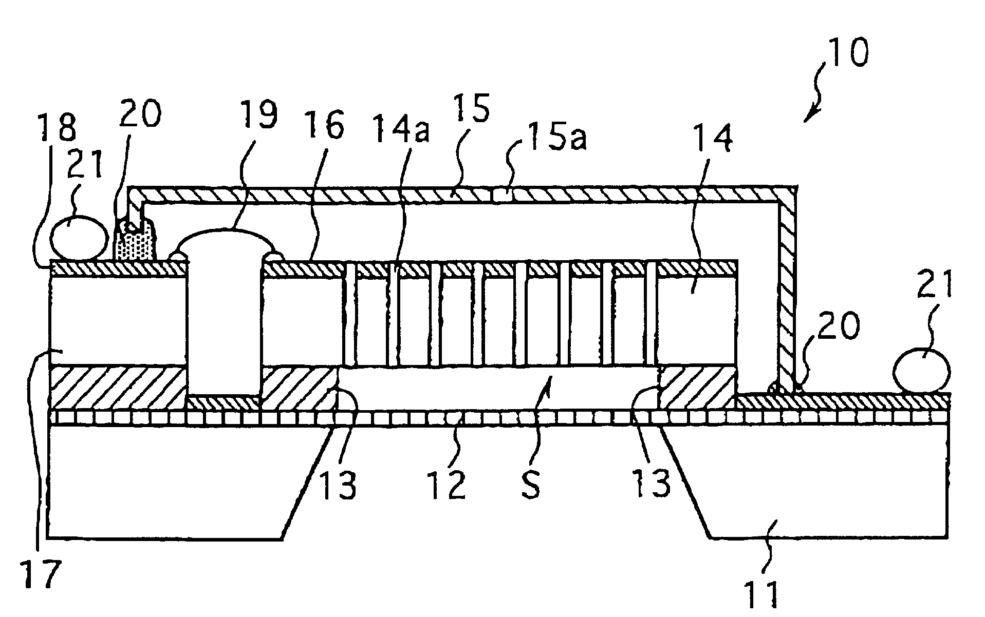
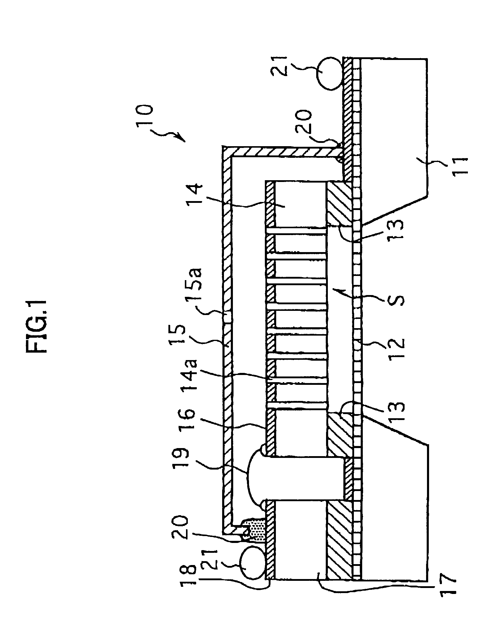
[0086]FIG. 12 is a diagram showing an example of an audio pickup apparatus according to the sound processing apparatus of the present invention. FIG. 13 is an illustrative diagram showing an example of the configuration of a chip microphone shown in FIG. 12.

[0087]In FIG. 12 and FIG. 13, a chip microphone 240 is configured to function as a condenser microphone by placing the adhesive support block 213 between the diaphragm 212 formed of the base 211 and the back plate 214 having the plurality of through holes 214a.

[0088]The chip microphone 240 is a condenser comprised of the thin, flat diaphragm 212 and the back plate 214. In order to provide more sensitive detection of changes in the condenser capacitance caused by the vibration of diaphragm 212 responding to changes in sound pressures, the following measures may be taken: (1) increasing a bias voltage; (2) decreasing a gap between the diaphragm 212 and the back plate 214; (3) increasing the plate areas of the diaphragm 212 and the...

fourth embodiment

[0111]FIG. 14 is a block diagram showing an example of the configuration of an audio transmission apparatus according to the sound processing apparatus of the present invention.

[0112]In FIG. 14, the audio transmission apparatus (sound processing apparatus) includes the chip microphone 240 and the oscillation / modulation circuit 241 connected to the chip microphone 240, and further includes an antenna 252 that is attached to the oscillation / modulation circuit 241 in place of the output terminal. The antenna 252 transmits radio waves to the air so that a remote apparatus can receive the radio waves.

[0113]The oscillation / modulation circuit 241 detects changes in the condenser capacitance of the chip microphone 240 as changes in the oscillation frequency. These changes in the oscillation frequency are regarded as FM modulations of the carrier frequency, and radio waves are transmitted from the antenna 252. A remote apparatus receiving the radio waves can demodulate the received radio wav...


PUM


Abstract

A chip microphone implemented as a single silicon-based chip includes a diaphragm which includes a vibration portion that vibrates in response to sound pressures, a support block which is formed on the diaphragm, excluding at least the vibration portion to provide a vibration space, and a back plate which is formed on the support block and over the vibration space, thereby facing the vibration portion of the diaphragm across the vibration space.

Description

BACKGROUND OF THE INVENTION[0001]1. Field of the Invention[0002]The present invention generally relates to microphones and apparatuses based on the use of microphones, and particularly relates to condenser microphones and apparatuses based on the use of such microphones.[0003]2. Description of the Related Art[0004]Technology has been making progress in terms of reducing the size and weight of electrical equipment, and sound processing apparatuses such as portable recorders and cellular phones are not an exception. Such sound processing apparatuses typically employ condenser microphones, which are comprised of two plates, i.e., a diaphragm and a back plate.[0005]Microphones of this kind provide superior performance in terms of sensitivity and noise robustness, and are suitable for size reduction. The diaphragm and the back plate are packed in a case with a spacer (support block) placed therebetween, thereby being provided as a single module, which is then implemented on a circuit boa...

Claims


Application Information

Patent Timeline
Patent Type & Authority Patents(United States)
IPC IPC(8): H04R3/00H04R19/00H04R25/00
CPCH04R19/005H04R31/00H04R1/04H04R19/04H04R25/407H04R31/006H04R2499/11H04R25/00
Inventor TAJIMA, TOSHIFUMINISHIGUCHI, TOSHIYUKISAITO, NOBUOMORITA, AKIRA
Owner NIPPON HOSO KYOKAI
Why Eureka
Try Eureka