Thin film transistor array panel and method for manufacturing the same
a thin film transistor and array panel technology, applied in non-linear optics, instruments, optics, etc., can solve the problems of high stress and resistivity, poor contact between drain electrode of al and pixel electrode of ito, and cr is not suitable for use in a large-scale lcd. , to achieve the effect of low resistivity, good contact characteristics and low resistan
- Summary
- Abstract
- Description
- Claims
- Application Information
AI Technical Summary
Benefits of technology
Problems solved by technology
Method used
Image
Examples
embodiment 1
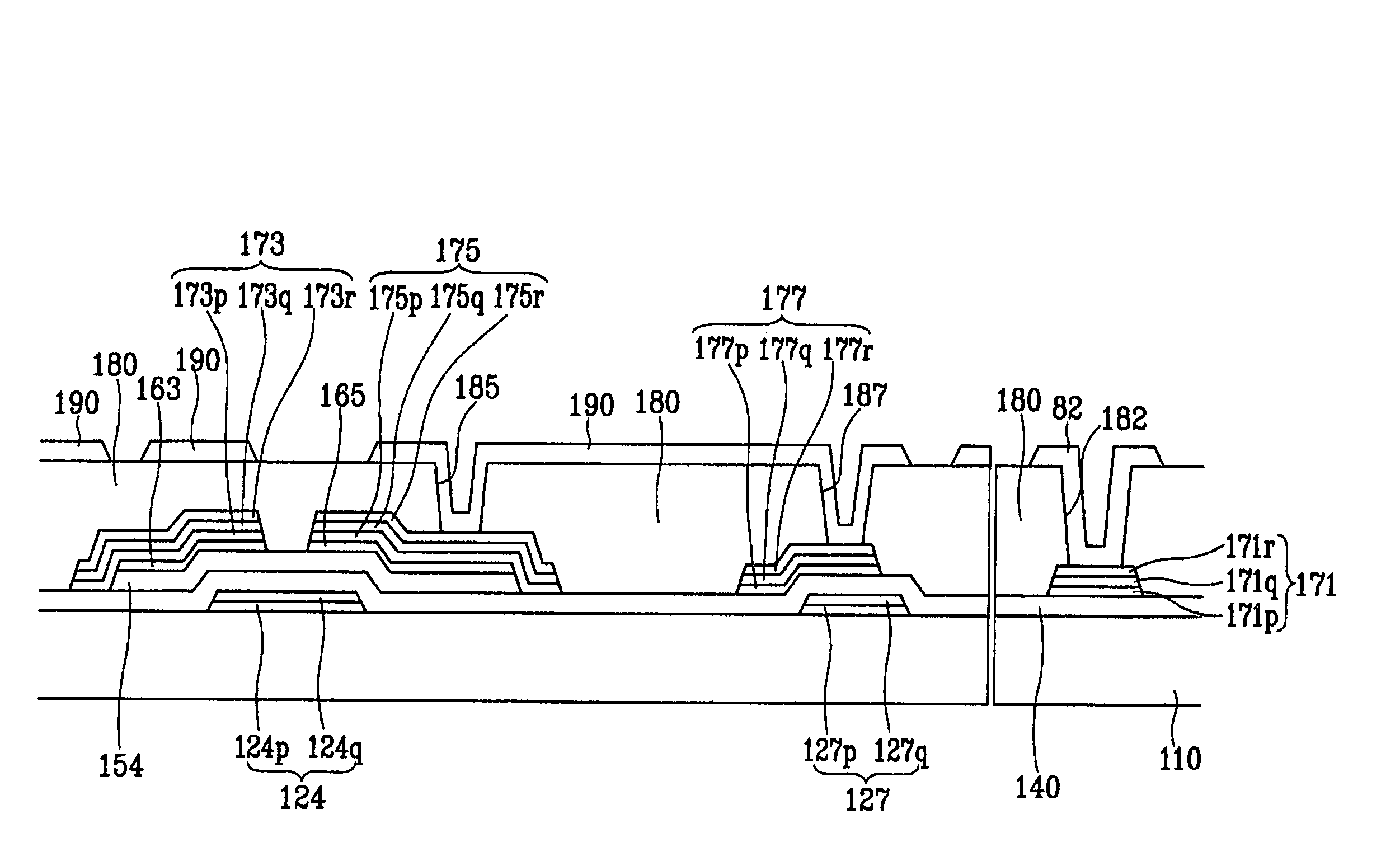
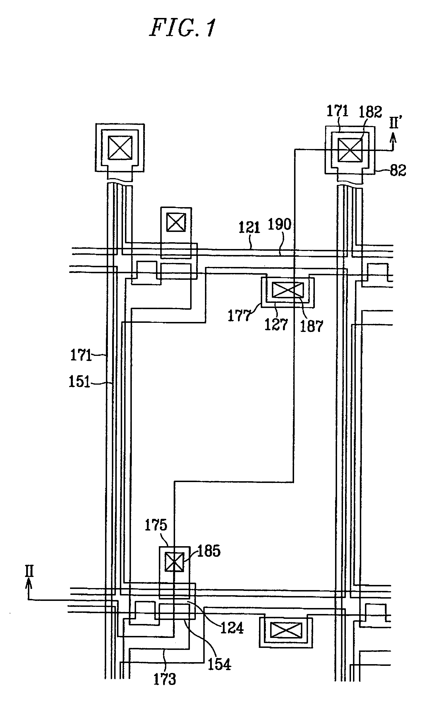
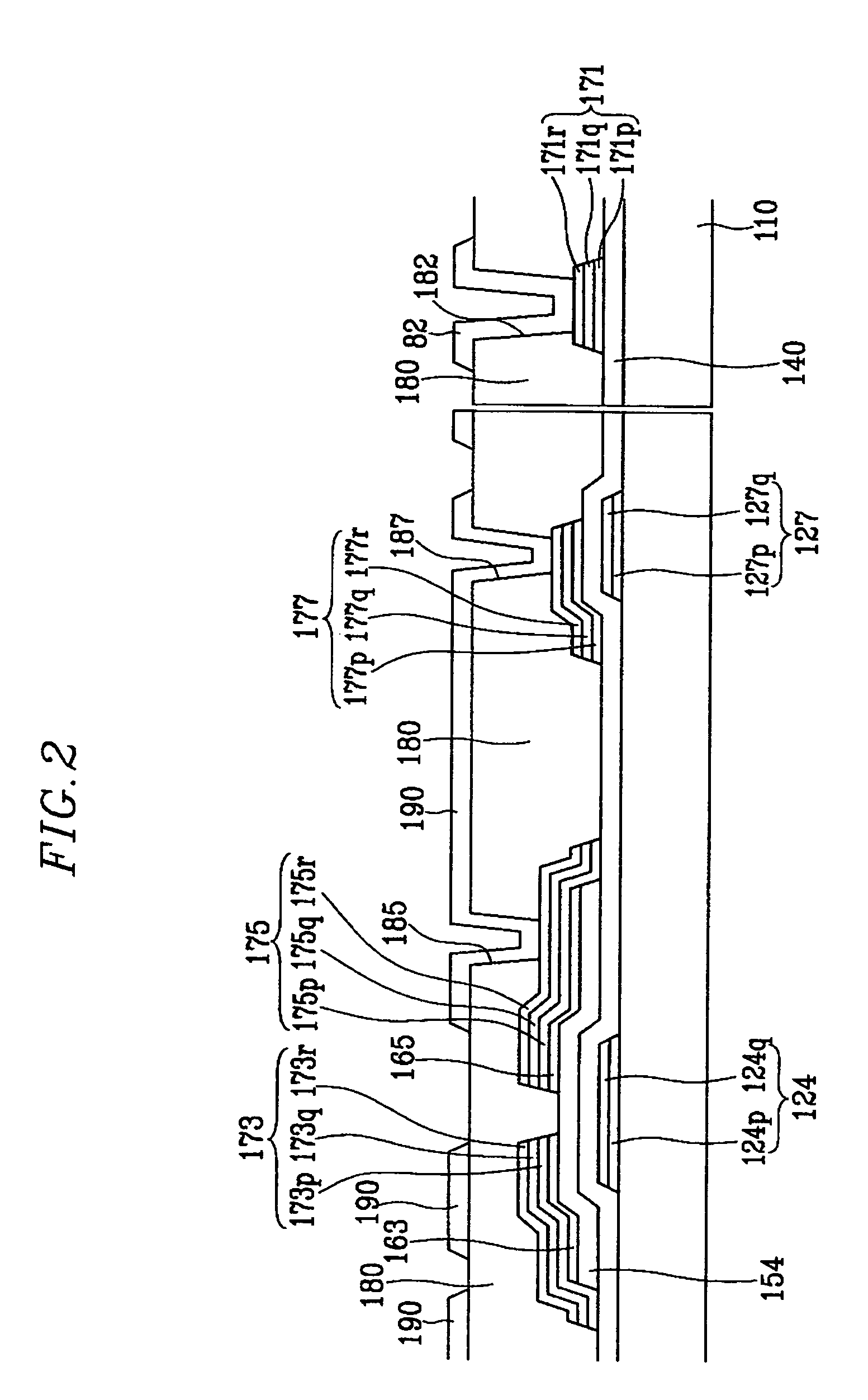
[0048]At first, a TFT array panel for an LCD according to a first embodiment of the present invention will be described in detail with reference to FIGS. 1 and 2.
[0049]FIG. 1 is a layout view of a TFT array panel for an LCD according to an embodiment of the present invention and FIG. 2 is a sectional view of the TFT array panel shown in FIG. 1 taken along the line II-II.
[0050]A plurality of gate lines 121 for transmitting gate signals are formed on an insulating substrate 110. The gate lines 121 are mainly formed in the horizontal direction and partial portions thereof become a plurality of gate electrodes 124. Also, different partial portions thereof that extend in a lower direction become a plurality of expansions 127.
[0051]The gate line 121 has lower layers 124p and 127p and upper layers 124q and 127q. The lower layers 124p and 127p are made of Al or an aluminum alloy such as aluminum-neodymium (Al—Nd). The upper layers 124q and 127q are made of a molybdenum alloy (Mo-alloy), whi...
embodiment 2
[0102]The data lines and the semiconductors are formed by different photo etching processes using different photo masks than in the first embodiment. However, the data lines and the semiconductors may be simultaneously formed by a photo etching process using a same photo mask to reduce production costs. Such an embodiment will be described in detail with reference to the drawings.
[0103]FIG. 7 is a layout view of a TFT array panel for an LCD according to another embodiment of the present invention. FIG. 8 is a sectional view of the TFT array panel shown in FIG. 7 taken along the line VIII-VIII′.
[0104]Referring to FIGS. 7 and 8, a plurality of gate lines 121, including a plurality of gate electrodes 124 and a plurality of storage electrode lines 131 which are electrically separated from the gate lines 121, are formed on a substrate 110.
[0105]The gate lines 121 and the storage electrode lines 131 have lower layers 121p and 131p and upper layers 121q and 131q. The lower layers 121p and ...
embodiment 3
[0140]The present embodiment illustrates a thin film transistor (TFT) array panel having color filters.
[0141]FIG. 14A is a layout view of a TFT array panel for an LCD according to another embodiment of the present invention. FIG. 14B is a sectional view of the TFT array panel shown in FIG. 14A taken along the line XIVB-XIVB′.
[0142]A plurality of gate lines 121 for transmitting gate signals are formed on an insulating substrate 110. The gate lines 121 are mainly formed in the horizontal direction and the partial portions thereof become a plurality of gate electrodes 124. Also, different partial portions thereof, which extend in a lower direction, become a plurality of expansions 127.
[0143]The gate line 121 has lower layers 124p and 127p and upper layers 124q and 127q. The lower layers 124p and 127p are made of aluminum (Al) or an aluminum alloy such as aluminum-neodymium (Al—Nd). The upper layers 124q and 127q are made of a molybdenum alloy (Mo-alloy: Mo—Nb, Mo—V, Mo—Ti), which is co...
PUM
| Property | Measurement | Unit |
|---|---|---|
| inclination angle | aaaaa | aaaaa |
| inclination angles | aaaaa | aaaaa |
| dielectric constant | aaaaa | aaaaa |
Abstract
Description
Claims
Application Information
 - R&D
- Intellectual Property
- Life Sciences
- Materials
- Tech Scout
- Unparalleled Data Quality
- Higher Quality Content
- 60% Fewer Hallucinations
Browse by: Latest US Patents, China's latest patents, Technical Efficacy Thesaurus, Application Domain, Technology Topic, Popular Technical Reports.
© 2025 PatSnap. All rights reserved.Legal|Privacy policy|Modern Slavery Act Transparency Statement|Sitemap|About US| Contact US: help@patsnap.com


