Optically controlled optical-path-switching apparatus, and method of switching optical paths

a technology of optical path switching and optical signal transmission apparatus, which is applied in the direction of optical elements, instruments, lenses, etc., can solve the problems of insufficient development of switches for practical use, low response speed of types of apparatus, and intrinsic problem of heat diffusion, etc., to achieve no dependence, high speed, and high durability

Inactive Publication Date: 2007-11-27
DAINICHISEIKA COLOR & CHEM MFG CO LTD +1
View PDF16 Cites 4 Cited by
  • Summary
  • Abstract
  • Description
  • Claims
  • Application Information

AI Technical Summary

Benefits of technology

[0013]The present invention advantageously provides an optically controlled optical-path-switching-type optical signal transmitting apparatus and a method of switching optical paths for optical signals, that do not suffer from the problems associated with use of an electric circuit or mechanical elements, that operate at a high speed, and that have high durability and no dependence on polarized electromagnetic waves.

Problems solved by technology

Apparatuses employing a thermo-optical effect created by using an electric heater to vary the refractive index of a waveguide of a Mach-Zehnder-interferometer-type optical waveguide switch are approaching practical application, but such apparatuses re disadvantageous in that this type of apparatus has a low response speed, of approximately 1 millisecond, and also requires an electric signal to operate the optical switch.
However, these switches cannot be said to be sufficiently developed for practical use because they have assignments such as that they have mechanically movable portions; they are dependent on polarized electromagnetic radiation, and other factors.
However, because, in all of the above methods, heat is produced using a heating resistor and a medium is heated using conduction, these methods have an intrinsic problem of diffusion of heat.
That is, because of the diffusion of heat, a fine thermal gradient cannot be provided over a large area and a desired distribution of the refractive index cannot not be easily or reliably obtained.
Furthermore, in actual practice, the fine processing of a heating resistor is limited, even when a photolithography technique used for semiconductor integrated circuits is employed, such that it is not possible to prevent the size of the device from increasing.
When the size of the device increases, the optical system becomes larger and more complicated.
Furthermore, because heat is produced using a heating resistor and the medium is heated by conduction of the heat, this invention has intrinsic disadvantages such as that the response is slow and the frequency for varying the refractive index cannot be increased.
Although this scheme is excellent in terms of controlling light using light, this scheme is constrained in that the angle of deflection must be within 30 degrees and, therefore, is problematic in that directions for switching optical paths cannot be freely set.

Method used


Image

  • Optically controlled optical-path-switching apparatus, and method of switching optical paths
  • Optically controlled optical-path-switching apparatus, and method of switching optical paths
  • Optically controlled optical-path-switching apparatus, and method of switching optical paths

Examples


example 1

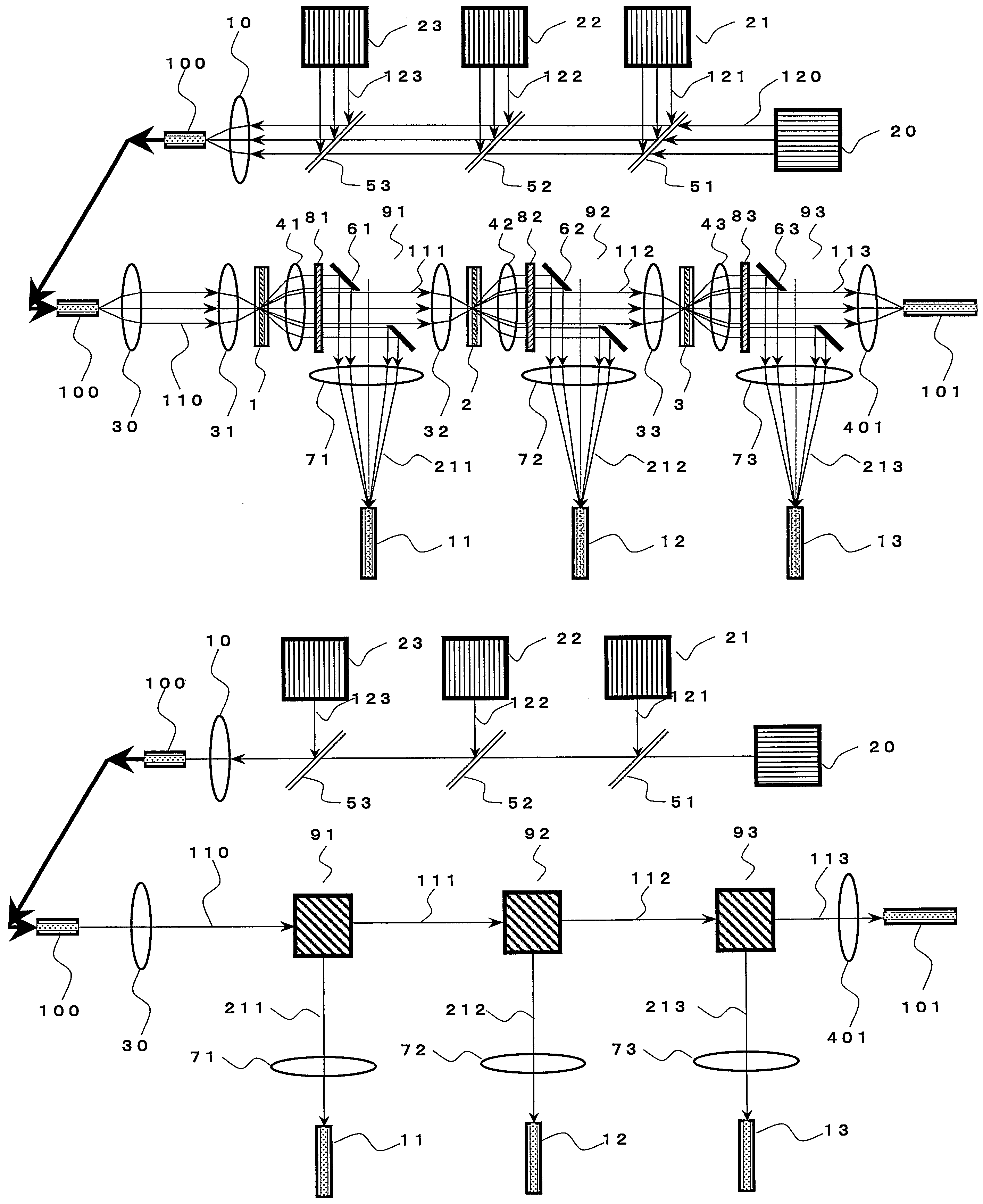
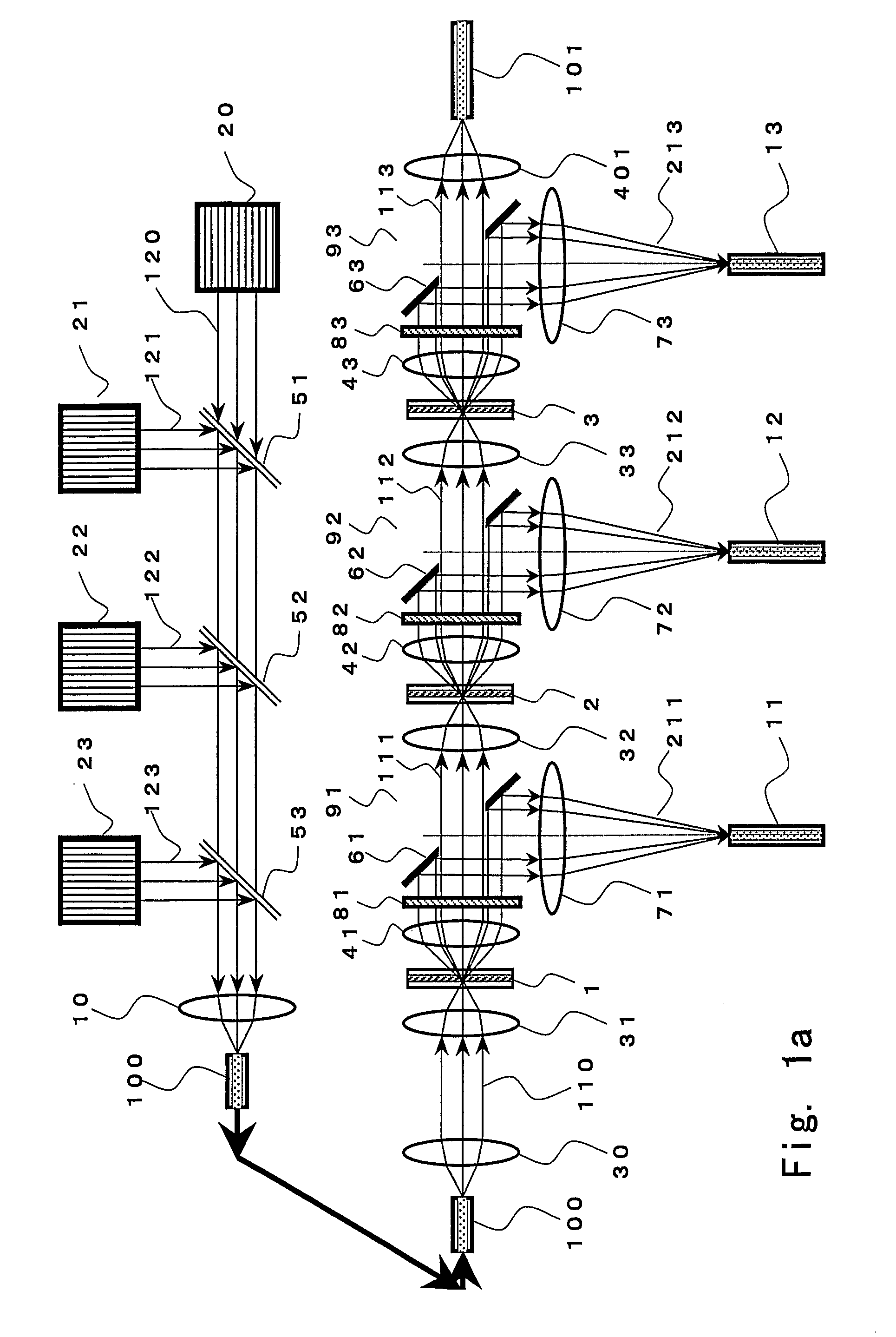
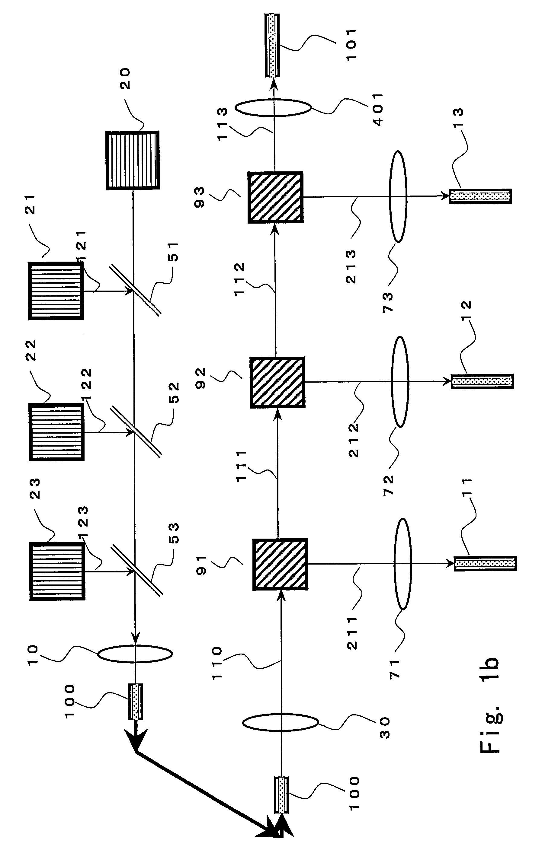
[0166]A schematic view of the configuration of an optically controlled optical-path-switching-type optical signal transmitting apparatus of Example 1 is shown in FIG. 1a. The optically controlled optical-path-switching-type optical signal transmitting apparatus of FIG. 1a exemplifies one (1) light source 20 for a signal light beam; three (3) light sources 21, 22, and 23 for control light beams having wavelengths that differ from each other and from the wavelength of the signal light beam 120; dichroic mirrors 51, 52, and 53 for aligning all the optical axes of and causing the signal light beam 120 and three (3) control light beams 121, 122, and 123 to propagate coaxially in the same direction; a condenser lens 10 for combining and causing the signal light beam 120 and the three (3) control light beams 121, 122, and 123 to enter an optic fiber 100; the optical fiber 100 for propagating the signal light beam 120 and the three control light beams 121, 122, and 123 together; a collimati...

example 2

[0201]FIG. 20 shows an example of the optical intensity distribution on a beam cross-sectional plane of the signal light beam, corresponding to the case of the optical configuration as shown in FIG. 8(b) and FIG. 10(b), and shows an optical intensity distribution on a beam cross-sectional plane of the signal light beam in the case where a focal point (light-condensed point) is set at the point 6 (on the exiting side of the light beam) close to the light-receiving lens 41 of the thermal lens forming device shown in FIG. 7(b) and the control light beam is irradiated. In such a case, the optical intensity in the central portion is stronger than the optical intensity in the central portion in the case where the control light beam is not irradiated (FIG. 18). In such a case, the optical intensity in the central portion of the cross-sectional plane of the signal light beam depends on the control light beams and the relation between the positions of the thermal lens forming device 1 and th...

example 3

[0210]The installation angle (45 degrees against the optical axis of the signal light beam 110) of the hole-provided mirror 61 in Example 1 is changed and, by determining the shape (the length of the major axis against that of the minor axis) of the elliptic hole 161 from calculation using trigonometric functions based on the installation angle, the angle of the optical path switching against the optical axis of the signal light beam 110 can be changed freely within a range from approximately 5 to 175 degrees. Installation angles of the hole-provided mirrors 62 and 63 in the second stage and the latter stages can similarly be changed.

[0211]Furthermore, by rotating the installation position of the hole-provided mirror 61 using the optical axis of the signal light beam 110 as a rotation axis and moving the position of the condenser lens 71, etc. the direction of the switching of the optical paths relative to the optical axis of the signal light beam 110 can be freely changed within a ...


PUM

PropertyMeasurementUnit
poweraaaaaaaaaa
angle of deflectionaaaaaaaaaa
wavelengthaaaaaaaaaa

Abstract

An optical signal optical path switching method comprising steps of using a thermal lens based on a distribution of refractive index produced reversibly caused by temperature increase generated in an area of the light-absorbing layer film of thermal lens forming devices 1, 2 and 3, that has absorbed control light beams 121, 122 and 123, and in the periphery thereof, causing the converged signal light beam to exit from the thermal lens forming device with an ordinary divergence angle when the control light beams 121, 122 and 123 have not been irradiated and no thermal lens has been formed, and causing the converged signal light beam to exit from the thermal lens forming device with a divergence angle larger than the ordinary divergence angle when the control light beams have been irradiated and a thermal lens has been formed, and causing the signal light beam to travel straight through holes 61, 62 and 63 of mirrors provided with the holes for the signal light beam to pass through when the control light beams have not been irradiated and no thermal lens has been formed, and changing the optical path by reflecting the signal light beam using the hole-provided mirror when the control light beams have been irradiated and a thermal lens has been formed.

Description

BACKGROUND OF THE INVENTION[0001]1. Field of the Invention[0002]The present invention relates to an optically controlled optical-path-switching-type optical signal transmission apparatus and to a method of switching optical paths for optical signals, that are used in the fields of optical communications and of optical information processing.[0003]2. Description of the Related Art[0004]In order to cope with the explosive increase of network traffic along with the expansion of the Internet and corporate and domestic intranets, an optical path switching apparatus not involving any electric signal (optical switch), i.e., a light-to-light direct switch is being sought. As an optical fiber, an optical waveguide, or an apparatus for or a method of switching courses for light beams propagating in space to travel, i.e., optical paths, schemes are known such as, for example, a space division scheme in which s optical paths are switched in an optical waveguide or between optical waveguides, a ...

Claims


Application Information

Patent Timeline
Patent Type & Authority Patents(United States)
IPC IPC(8): G02F1/03G02B27/12G02B27/14G02B3/10G02B6/00G02F1/01G02F1/29G02F1/295G02F1/31G02F1/33H04Q11/00
CPCG02F1/293H04Q11/0005G02F1/0126G02F1/0147H04Q2011/0041H04Q2011/0024H04Q2011/0026G02F1/29G02F1/31H04Q11/00
Inventor TANAKA, NORIOUENO, ICHIROHIRAGA, TAKASHITANIGAKI, NOBUTAKAMIZOKURO, TOSHIKOYAMAMOTO, NORITAKAMOCHIZUKI, HIROYUKI
Owner DAINICHISEIKA COLOR & CHEM MFG CO LTD
Why Eureka
Try Eureka