Method for measurement of gas flow velocity, method for energy conversion using gas flow over solid material, and device therefor

a gas flow velocity and gas flow technology, applied in the direction of liquid/fluent solid measurement, generator/motor, instruments, etc., can solve the problems of limited application of this method, dependant method, large equipment required (lasers, ccd cameras) and large size of equipment, etc., to achieve low response time, small construction size, and low cost

Inactive Publication Date: 2007-12-04
INDIAN INSTITUTE OF SCIENCE
View PDF8 Cites 6 Cited by
  • Summary
  • Abstract
  • Description
  • Claims
  • Application Information

AI Technical Summary

Benefits of technology

[0021]It is yet another object of the invention to provide a method for the determination of flow velocities which does not require any external seeding with colloidal particles of determinate size in the gas and is not susceptible to variations in external parameters at a particular flow plane or viscosity.
[0023]It is yet another object of the invention to provide a flow sensing device for measurement of flow velocities of gases which is operable even at very low flow velocities with accuracy in measurement and low response times.
[0024]It is a further object of the invention to provide a flow sensing device which by its simplicity and small size of construction is economical, does not result in any turbulence in the gas flow thereby ensuring accuracy in flow velocity measurement, and is impervious to variations in external parameters such as ambient temperature.
[0025]It is another object of the invention to provide a flow sensing device which is operable irrespective of the nature of the gas (whether clear or turbid, high or low viscosity) with accuracy in measurement and low response times.
[0028]It is a further object of the invention to provide an energy conversion device which by its simplicity of construction is economical, does not result in any turbulence in the gas flow thereby ensuring accuracy in flow velocity measurement, and is impervious to variations in external parameters such as gas or ambient temperature.

Problems solved by technology

However, this method has several disadvantages.
The primary disadvantage is the underlying assumption that the movement of all the colloidal particles assume the direction of the flow.
Thus, the application of this method is limited to velocities of greater than 2 cm / s.
The equipment required (lasers, CCD cameras) is also large in size.
Another disadvantage is that the method is dependant entirely on image analysis and thereby on the analysis algorithms.
Since the particle imaging velocimetry method measures the velocity of the colloidal particles and there is no direct digital signal corresponding to the gas velocity; the flow velocity of pure gas cannot be measured.
The method also is not appropriate for systems where optical access is absent.
Another disadvantage is that the equipment required such as lasers and charge coupled devices are expensive.
However, this method also suffers from several disadvantages.
This method also requires large and expensive equipment such as a plurality of lasers and digital counters.
Another significant disadvantage of this method is that it is restricted to a single point measurement.
This method also does not work in systems where optical access to the gas flow path at the measurement volume is absent.
As a result while the Mie scattering intensity is substantially better in the forward direction, it is difficult to set up forward receiving optics which remain aligned to the moving measurement volume.
Greater noise at higher speed with radio frequency interference is possible.
However, in this method a slight variation in the temperature, pressure or composition of the fluid under study can result in erroneous readings.
In addition, even such compensating electronics can be subject to error.
At low velocities, the convention currents in the gas cause a malfunction in the sensor.
As a result they are not suitable for example, in biological systems.
The equipment size is also large rendering it expensive.
Thus it is not suitable for systems which involve small volumes of fluids flowing at low flow velocity.
Nuclear power plants require expensive safety equipment and measures in view of the potential for radiation leakage.
Thermal power plants use fossil fuels, which result in the attendant problems of pollution and also suffer from reduced supplies due to depletion of fossil fuels and oil.
The equipment required is also expensive and occupies a large area.
However, the magnitude of the power generated in relation of the size of the device renders it unsuitable for use for large scale energy conversion.
However, this method has the disadvantages of requiring a high degree of capital investment and space.
However, this phenomenon was specific to one-dimensional nature of the carriers in the nano-tubes and was absent in other solid material such as graphite or semi-conductors.

Method used


Image

  • Method for measurement of gas flow velocity, method for energy conversion using gas flow over solid material, and device therefor
  • Method for measurement of gas flow velocity, method for energy conversion using gas flow over solid material, and device therefor
  • Method for measurement of gas flow velocity, method for energy conversion using gas flow over solid material, and device therefor

Examples


example 1

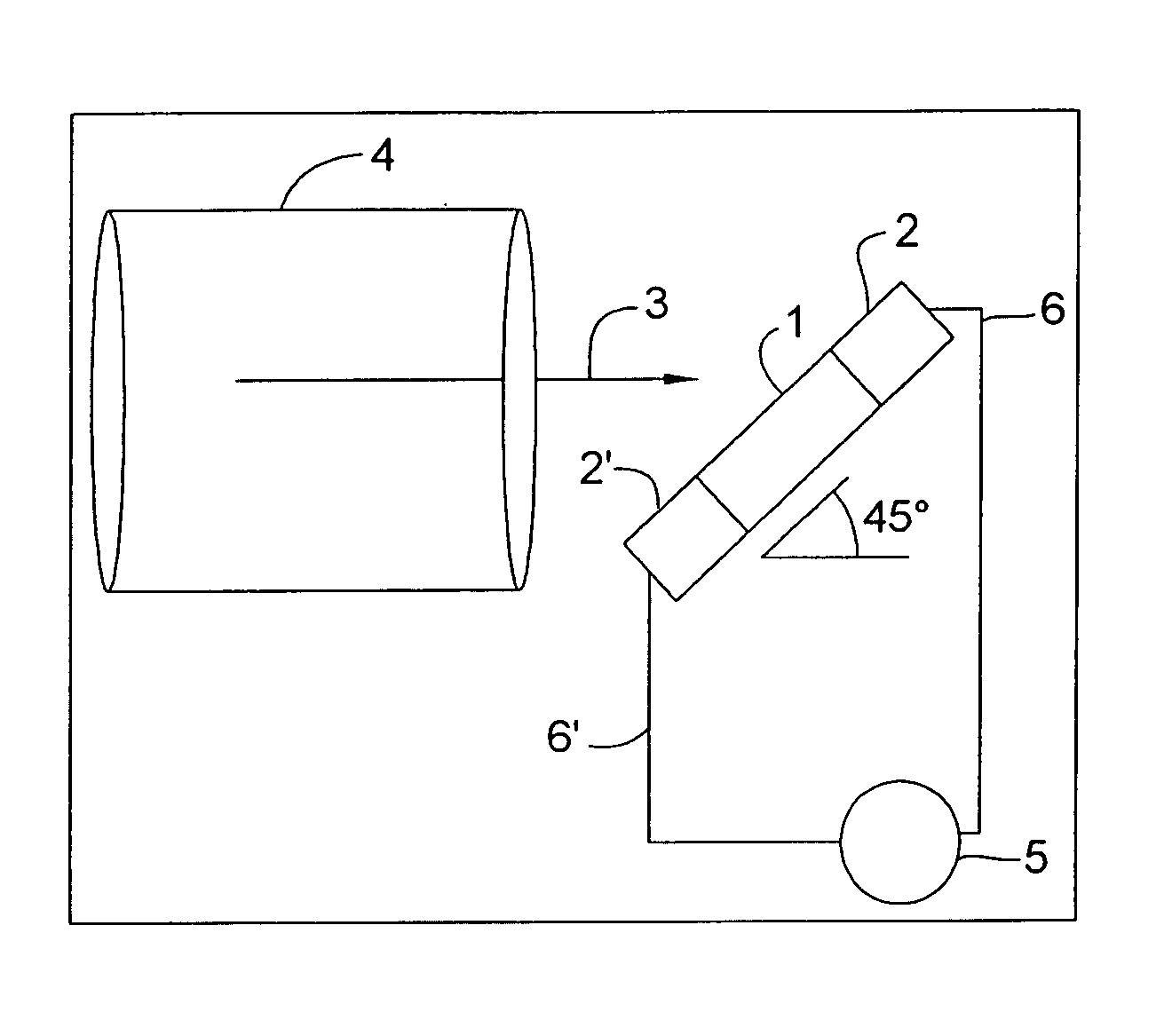
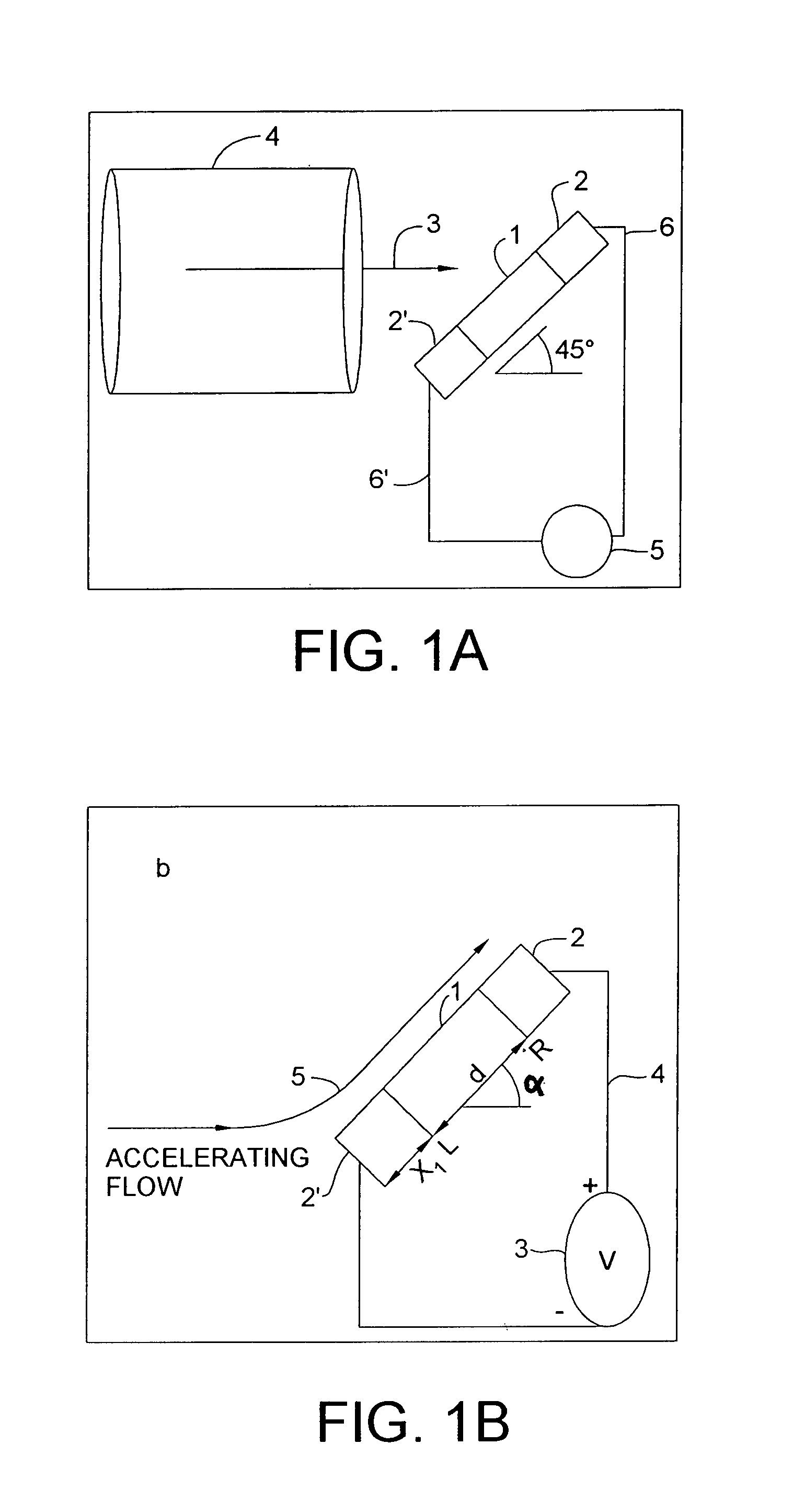
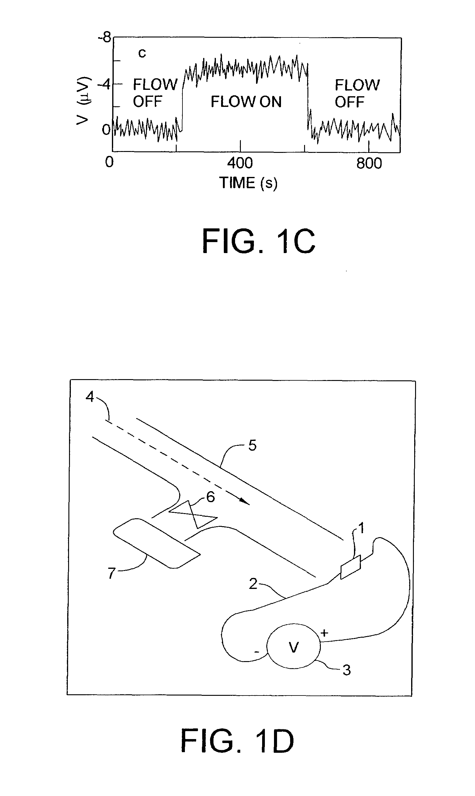
[0133]FIG. 1(d) shows a schematic layout of the experimental set up used in example 1 to achieve a calibrated gas flow velocity in the flow sensing device of the invention. Flow sensing devices comprising 3×10⁻³ m along the gas flow and 1×10⁻³ m perpendicular to the gas flow were used. The flow sensing elements were made of n-type Ge (Sb doped, ρ=0.01 Ωm), n-Si (ρ=0.01 Ωcm), p-Si (ρ=0.01 Ωcm), single wall carbon nanotubes, multi-wall carbon nanotubes, graphite and polycrystalline copper. The electrical contacts comprised of copper leads of 125×10−6 m diameter made using silver emulsion (shown in the shaded region in FIG. 1(b)). The exposed area of the flow sensor element is not covered by the silver emulsion and was about 2×10⁻³ m along the flow and 1×10⁻³ m perpendicular to the flow of the gas. The sensing elements comprising single wall carbon nanotubes, multi-wall carbon nanotubes, and graphite were prepared by densely packing the powder between the two electrodes. The dimensions...

example 2

[0136]The same set up as in Example 1 was repeated except that the flow sensor element was kept at a distance of 2×10⁻² m from the exit point or 1×10⁻² m outside the tube. The results obtained were similar to those in Example 1.

example 3

[0137]The same experiment was repeated as in Example 1 except that the material in question was a solid polycrystalline copper sheet for which the slope of A was very small. The results are given in Table 1.

[0138]A comparison of the various results obtained show that the signal for p-type Si and SWNT are opposite to that for n-type Si, n-Ge, graphite and copper. SWNT samples are usually unintentionally p-doped (Hone et al, Phys. Rev. Lett., 80, 1042, 1998 [4]; and Collins et al, Science, 287, 1801, 2000) [3]. This explains the sign of the flow induced voltage being the same for SWNT and p-Si. The inset of FIG. 3 shows the plot of the slope A versus the Seebeck coefficients (S) of the solid materials used. The coefficient A depends linearly on S as shown by the fitted line in the inset with slope=60K.


PUM


Abstract

The present invention relates to a method for energy conversion by gas flow over solid materials and also to a method for measurement of velocity of a gas flow over solid material such as doped semiconductors, graphite, and the like as a function of the 5 electricity generated in the solid material due to the flow of the gas along the surface thereof using a combination of the Seebeck effect and Bernoulli's principle.

Description

FIELD OF THE INVENTION[0001]The present invention relates to a method for energy conversion by gas flow over solid materials. More particularly, the present invention relates to a method for the generation of voltage and current by gas flow over solid material such as doped semiconductors, graphite, and the like. In particular, the present invention also relates to a method for the conversion of energy by a gas flow over a solid material using a combination of the Seebeck effect and Bernoulli's principle. The present invention also relates to a method for the measurement of velocity of a gas along the flow thereof as a function of the electricity generated in the solid material due to the flow of the gas along the surface thereof.BACKGROUND OF THE INVENTION[0002]The measurement of gas velocity along the direction of flow is of significant importance in several applications. For example, an accurate determination of wind velocity over oceans or rivers along the direction of the flow ...

Claims


Application Information

Patent Timeline
Patent Type & Authority Patents(United States)
IPC IPC(8): G01F1/68G01F1/20G01F1/64G01F1/684G01F1/688H02N11/00
CPCB82Y10/00G01F1/20H02N11/002G01F1/688G01F1/64G01P5/00B82Y30/00
Inventor SOOD, AJAY KUMARGHOSH, SHANKAR
Owner INDIAN INSTITUTE OF SCIENCE
Why Eureka
Try Eureka