Stacked solid electrolytic capacitor

a technology of electrolytic capacitors and solids, which is applied in the direction of stacked capacitors, casings/cabinets/drawers, electrical equipment casings/cabinets/drawers details, etc., can solve the problems increased leakage current, and some defects in epoxy molding, so as to reduce the risk of electrical short circuit, high sealing performance, and high humidity resistance

Inactive Publication Date: 2007-12-25
NICHICON CORP
View PDF9 Cites 39 Cited by
  • Summary
  • Abstract
  • Description
  • Claims
  • Application Information

AI Technical Summary

Benefits of technology

[0008]The present invention provides a thinned stacked solid electrolytic capacitor having high humidity resistance.
[0010]With the above-mentioned configuration, the capacitor element is covered with the metal cap. The metal cap has high sealing performance, and shields against external environment. In this case, it is possible to obtain high humidity resistance. It is possible to restrain a degradation of property of the solid electrolytic capacitor. It is possible to reduce ESL of the solid electrolytic capacitor because the metal cap and the substrate act as a cathode.

Problems solved by technology

There is, however, some defects with respect to the epoxy molding.
And it is possible that a leakage current is increased and electrical short circuit is generated.
And the property is possibly degraded because of separation of a polymer.
It is, however, difficult to obtain humidity resistance because a molding material is epoxy resin, with respect to a solid electrolytic capacitor manufactured following the art of Document 1.

Method used


Image

  • Stacked solid electrolytic capacitor
  • Stacked solid electrolytic capacitor
  • Stacked solid electrolytic capacitor

Examples


first embodiment

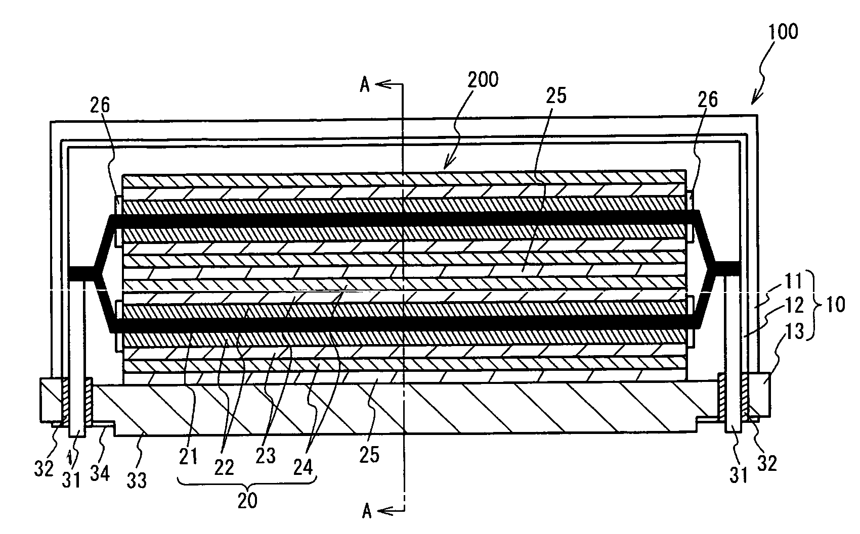
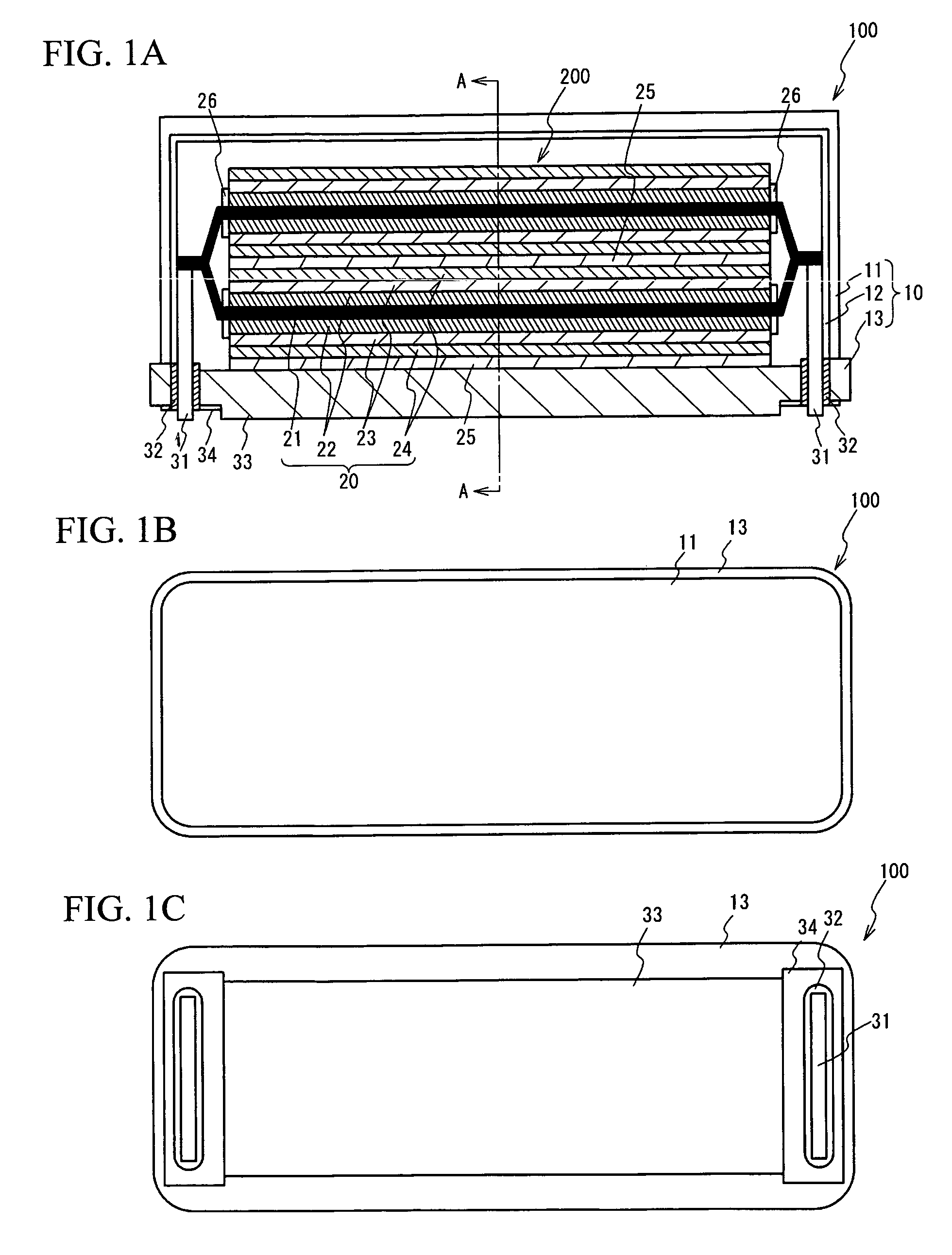
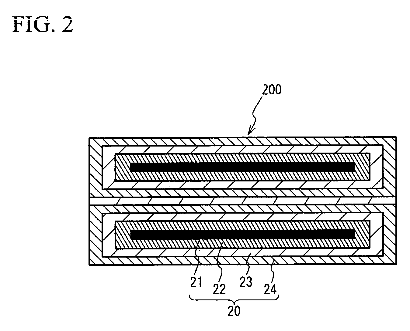
[0018]FIG. 1A through FIG. 1C illustrate a stacked solid electrolytic capacitor 100 in accordance with a first embodiment of the present invention. FIG. 1A illustrates a cross sectional view of the solid electrolytic capacitor 100. FIG. 1B illustrates a top view of the solid electrolytic capacitor 100. FIG. 1C illustrates a bottom view of the solid electrolytic capacitor 100. As shown in FIG. 1A, the solid electrolytic capacitor 100 has a structure in which a capacitor element 200 is packaged in a case 10.

[0019]As shown in FIG. 1A and FIG. 1B, the case 10 has a structure in which a metal cap 11 is provided on a base substrate 13. The metal cap 11 may be seam welded to the base substrate 13. The metal cap 11 is composed of a metal such as copper, aluminum, SPC steel, cobalt steel or stainless steel.

[0020]The base substrate 13 has electrical conductivity, can be soldered easily, and is composed of a material having low moisture permeability. The base substrate 13 is, for example, comp...

second embodiment

[0032]FIG. 3A through FIG. 3C illustrate a solid electrolytic capacitor 100a in accordance with a second embodiment of the present invention. FIG. 3A illustrates a cross sectional view of the solid electrolytic capacitor 100a. FIG. 3B illustrates a top view of the solid electrolytic capacitor 100a. FIG. 3C illustrates a bottom view of the solid electrolytic capacitor 100a. As shown in FIG. 3A through FIG. 3C, the solid electrolytic capacitor 100a has a capacitor element 200a instead of the capacitor element 200, being different from the solid electrolytic capacitor 100.

[0033]The capacitor element 200a has a structure in which a plurality of unit elements 20a are stacked. The unit element 20a has a structure in which the solid electrolyte layer 22 and a cathode foil 27 is stacked on the upper face and on the lower face of an anode foil 21a. Two unit elements 20a are stacked in the capacitor element 200a in the embodiment. The capacitor element 200a is adhered to the base substrate 13...

example 1

[0041]In an example 1, the solid electrolytic capacitor 100 shown in FIG. 1A through FIG. 1C was fabricated. Aluminum foil, which was subjected to an etching treatment and a chemical conversion treatment, was used as the anode foil 21. The aluminum foil was cut out into the anode foil 21. The anode foil 21 was subjected to a chemical conversion treatment at a voltage near a formation voltage of the dielectric oxide layer of the anode foil 21 using chemical liquid mainly containing 0.5% to 2% ammonium adipate by weight, and was subjected to a thermal treatment in a temperature range 200 degrees C. to 280 degrees C. The thickness of the anode foil 21 was 100 μm to 110 μm.

[0042]Next, the solid electrolyte layer 22 was formed on both faces of the anode foil 21. A solvent containing 25 wt % monomer and a solvent containing 60 wt % oxidizer were provided on the both faces of the anode foil 21 and in the separator. The solvents were heated from 30 degrees C. to 150 degrees C. The thickness...


PUM

PropertyMeasurementUnit
wt %aaaaaaaaaa
thicknessaaaaaaaaaa
thicknessaaaaaaaaaa

Abstract

A stacked solid electrolytic capacitor has a substrate, a capacitor element, and a metal cap. The substrate has electrical conductivity. The capacitor element is provided on the substrate. The metal cap is coupled to the substrate, covers the capacitor element and is electrically conducted to the substrate. A cathode of the capacitor element is electrically conducted to the substrate.

Description

BACKGROUND OF THE INVENTION[0001]1. Field of the Invention[0002]This invention generally relates to a stacked solid electrolytic capacitor.[0003]2. Description of the Related Art[0004]A solid electrolytic capacitor attracts attentions because the capacitor is superior in frequency property compared to other electrolytic capacitors. A roll-formed solid electrolytic capacitor, a stacked solid electrolytic capacitor and so on are used as the solid electrolytic capacitor. An exterior of the stacked solid electrolytic capacitor is, generally, molded with epoxy resin. There is, however, some defects with respect to the epoxy molding.[0005]Transfer molding is, generally, used as an epoxy molding method. The epoxy resin is heated to more than 150 degrees C. and the epoxy resin is put into with a pressure of more than few atmospheres, in the method. Polymerized element is subjected to much stress. And it is possible that a leakage current is increased and electrical short circuit is generate...

Claims


Application Information

Patent Timeline
Patent Type & Authority Patents(United States)
IPC IPC(8): H01G9/10H05K5/03
CPCH01G9/06H01G9/15H01G9/14H01G9/08H01G4/30
Inventor ISHIZUKA, HIDETOSHIFUNAHASHI, MINORUMIZUTANI, TOSHIYUKIUEDA, AKIRAYAMADA, KATSUHARU
Owner NICHICON CORP
Why Eureka
Try Eureka