Fiber laser, spontaneous emission light source and optical fiber amplifier

a fiber laser and light source technology, applied in the field of fiber lasers, spontaneous emission light sources, optical fiber amplifiers, can solve the problems of laser oscillation not being achieved, oscillation efficiency decreasing, etc., and achieves the effects of low cost, low cost, and low cos

Active Publication Date: 2007-12-25
NIPPON TELEGRAPH & TELEPHONE CORP
View PDF5 Cites 8 Cited by
  • Summary
  • Abstract
  • Description
  • Claims
  • Application Information

AI Technical Summary

Benefits of technology

[0027]To accomplish the foregoing objects, the present invention is characterized by the following two features.
[0033]2) It can implement the highly reliable, practical fiber laser, ASE source and optical fiber amplifier operating at the 2.3 μm band with little degradation in the fiber characteristics due to the photo darkening because it utilizes the 1.2 μm band (1.2 μm band excitation) as the excitation wavelength to be launched into the Tm-doped fiber.
[0033]2) It can implement the highly reliable, practical fiber laser, ASE source and optical fiber amplifier operating at the 2.3 μm band with little degradation in the fiber characteristics due to the photo darkening because it utilizes the 1.2 μm band (1.2 μm band excitation) as the excitation wavelength to be launched into the Tm-doped fiber.

Problems solved by technology

The loss increase of FIG. 2 is due to defects produced in the glass of the fluoride fiber by launching the laser beam into the fiber.
Accordingly, considering the 2.3 μm band operation laser applications employing the Tm-doped fluoride fibers utilizing the 0.67 μm or 0.8 μm excitation, there arises a problem in the reliability in that the oscillation efficiency decreases with time, and finally the laser oscillation cannot be achieved.
Accordingly, using such a conventional light source for the application to a noninvasive blood glucose evaluation equipment or the like cannot make a reliable, practical light source.

Method used


Image

  • Fiber laser, spontaneous emission light source and optical fiber amplifier
  • Fiber laser, spontaneous emission light source and optical fiber amplifier
  • Fiber laser, spontaneous emission light source and optical fiber amplifier

Examples


embodiment 1

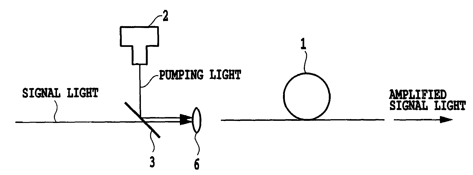
[0076]In the first embodiment in accordance with the present invention, applications of the present invention to the 2.3 μm band and 1.8 μm band fiber lasers will be described. FIG. 10 shows a configuration of the first embodiment in accordance with the present invention. In FIG. 10, the reference numeral 1 designates a Tm3+-doped fiber serving as a gain medium; 2 designates a 1.2 μm band pumping source (consisting of a semiconductor laser with an oscillation wavelength of 1.21 μm, and a maximum output of 200 mW); 3 designates a dichroic mirror (that reflects 1.2 μm band light and transmits 1.6–2.4 μm band light); 4 designates a reflecting mirror (with the reflectance of 50% at 1.6–2.4 μm band, but transmits 100% of the 1.2 μm band light); 5 designates a 2.3 μm band and 1.8 μm band band-pass filter (with the transmission characteristics as illustrated in FIGS. 11A and 11B); 6 designates a condenser lens; and 7 designates a total reflection mirror (with the reflectance of 95% or more...

embodiment 2

[0089]In the second embodiment in accordance with the present invention, application of the present invention to a 2.3 μm band optical fiber amplifier will be described. FIG. 13 shows a configuration of the second embodiment in accordance with the present invention. In FIG. 13, the reference numeral 1 designates a Tm3+-doped fiber serving as a gain medium; 2 designates a 1.2 μm band pumping source (consisting of a semiconductor laser with an oscillation wavelength of 1.21 μm, and a maximum output of 200 mW); 3 designates a dichroic mirror (that reflects 1.2 μm band light and transmits 1.6–2.4 μm band light); and 6 designates a condenser lens.

[0090]Using the following fibers as the gain medium 1 was able to implement the following signal gains respectively:[0091]Using the Tm-doped fluoride fiber (with Tm additive density of 2000 wt. ppm, relative refractive index difference of 1.6%, and fiber length of 11 m) was able to achieve the signal gain of 8.3 dB for the 2.205 μm signal light ...

embodiment 3

[0098]In the third embodiment in accordance with the present invention, application of the present invention to a 2.3 μm band spontaneous emission source will be described. FIG. 14 shows a configuration of the third embodiment in accordance with the present invention. In FIG. 14, the reference numeral 1 designates a Tm3+-doped fiber serving as a gain medium; 2 designates a 1.2 μm band pumping source (consisting of a semiconductor laser with an oscillation wavelength of 1.21 μm, and a maximum output of 200 mW); 3 designates a dichroic mirror (that reflects 1.2 μm band light and transmits 2.2 μm band light); and 6 designates a condenser lens.

[0099]The configuration of FIG. 14 enables the Tm3+-doped fluoride fiber, Tm3+-doped tellurite fiber, Tm3+-doped germanate hydroxide glass fiber, Tm3+-doped chalcogenide glass fiber, Tm3+-doped bismuth based glass fiber and Tm3+-doped fluorophosphate glass fiber to achieve the spontaneous emission characteristics as illustrated in FIGS. 7 and 8. T...


PUM


Abstract

New fiber lasers, spontaneous emission sources, and optical fiber amplifiers are provided. Their conventional counterparts, which have a fiber doped with thulium (Tm) ions and excited by 0.67 μm or 0.8 μm pumping light, have a problem in that their characteristics are deteriorated with the elapse of time. The new fiber lasers, spontaneous emission sources, and optical fiber amplifiers use 1.2 μm light as pumping light. Alternatively, they use a pumping source for exciting the thulium from the lowest energy level 3H6 to 3H5 excitation level. As a more preferable configuration, they improve the emission efficiency at 2.3 μm band by disclosing Tm-doped host glass.

Description

TECHNICAL FIELD[0001]The present invention relates to a fiber laser, spontaneous emission light source, and optical fiber amplifier, and particularly to the fiber laser, spontaneous emission light source, and optical fiber amplifier that operate near a 2 μm band with using as the gain medium an optical fiber having a core or a cladding doped with a rare-earth element having a laser transition level.BACKGROUND ART[0002]FIG. 1 is an energy level diagram of a thulium ion (see, non-patent document 1). In FIG. 1, energy values are shown on the right side of individual energy levels, and names of the individual levels are shown on the left side of the individual energy levels. Numerals added to arrows indicate wavelengths of light lasored (corresponding to upward arrows (not shown in FIG. 1)) or emitted (corresponding to downward arrows in FIG. 1) when transitions of the individual arrows occur. Here, the unit of the energy is represented by 1 / cm (corresponding to Kayser in terms of spect...

Claims


Application Information

Patent Timeline
Patent Type & Authority Patents(United States)
IPC IPC(8): G02B6/02H01S3/067H01S3/091H01S3/00H01S3/094H01S3/0941H01S3/16H01S3/17
CPCH01S3/06716H01S3/005H01S3/094003H01S3/177H01S3/1616H01S3/175H01S3/176H01S3/0941
Inventor YAMADA, MAKOTOAOZASA, SHINICHISAKAMOTO, TADASHIMORI, ATSUSHISHIKANO, KOUJISHIMIZU, MAKOTO
Owner NIPPON TELEGRAPH & TELEPHONE CORP
Why Eureka
Try Eureka