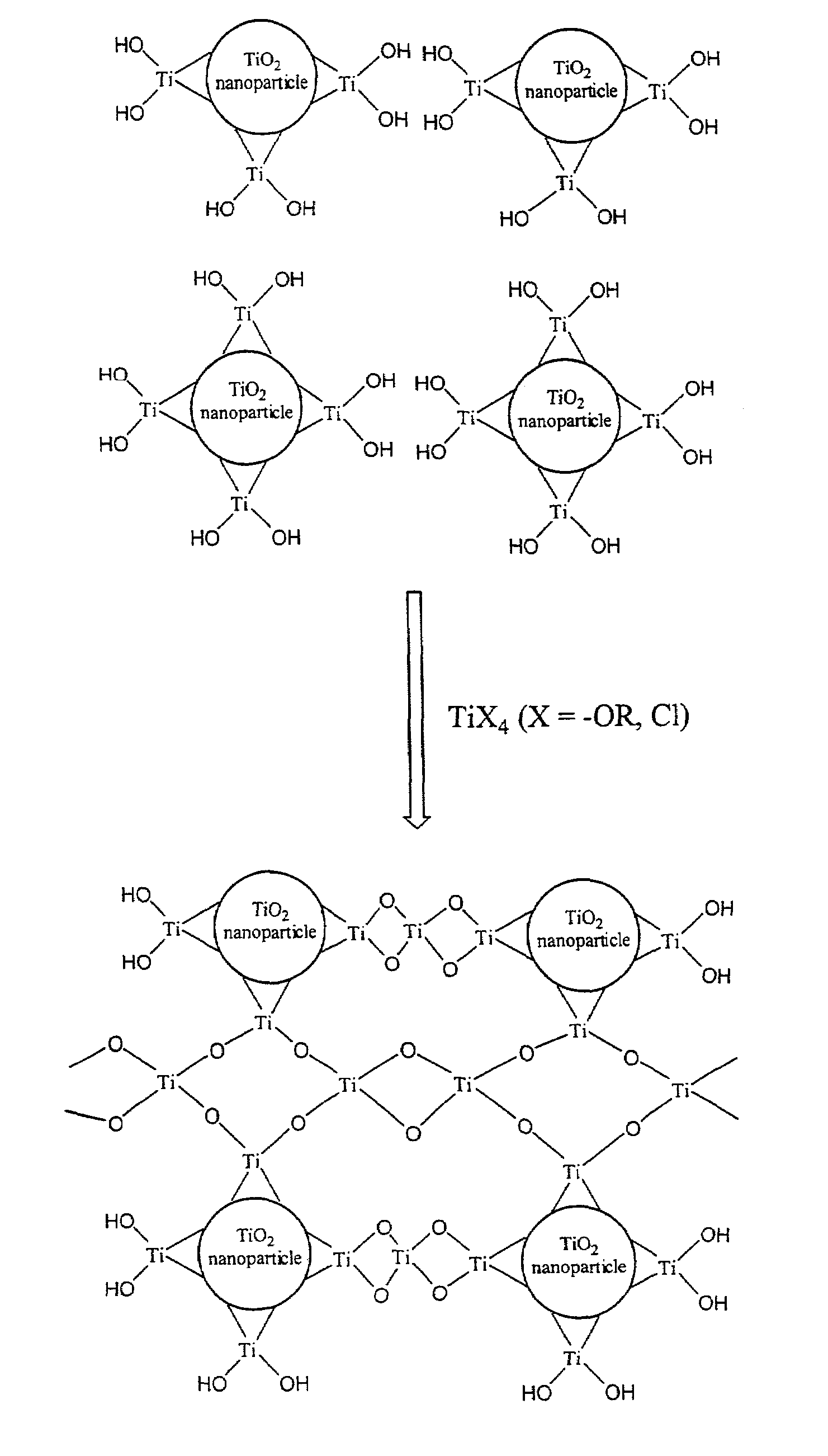
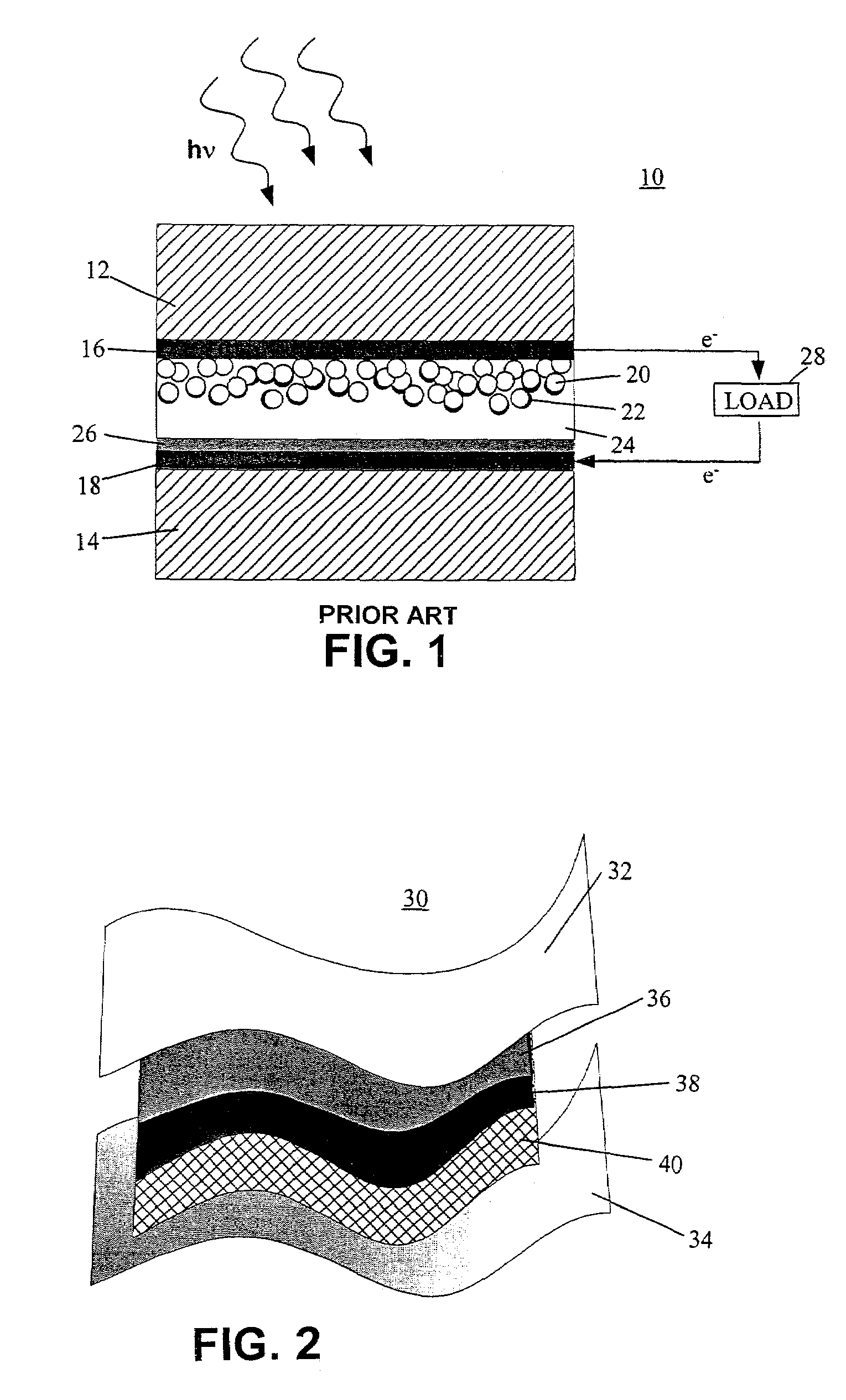
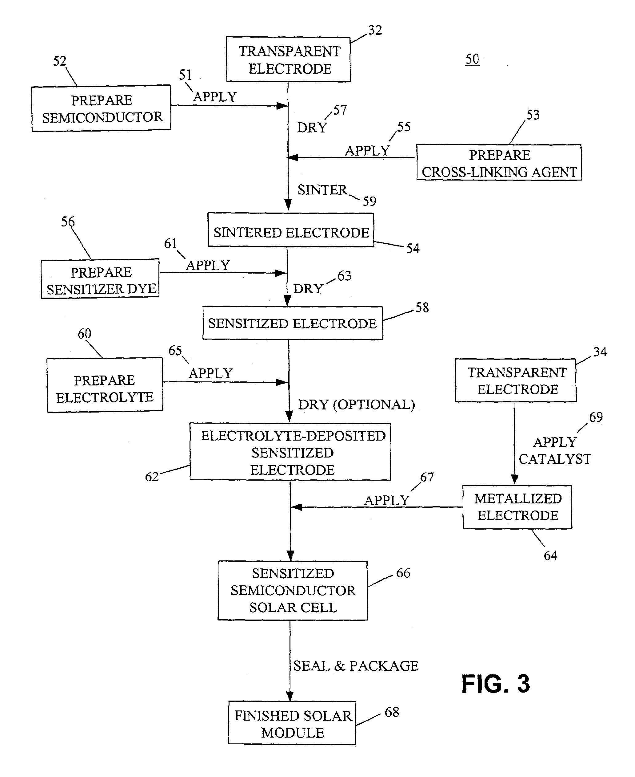
Photovoltaic cell

a photovoltaic cell and cell technology, applied in the field of photovoltaic cells, can solve the problems of limited use of certain components of photovoltaic cells, limited selection of manufacturing processes, and limited use of useable materials, so as to increase the selection of materials, improve the quality of photovoltaic cells, and reduce the effect of temperature stability

Inactive Publication Date: 2008-01-29
MASSACHUSETTS LOWELL UNIV OF +1
View PDF30 Cites 13 Cited by
  • Summary
  • Abstract
  • Description
  • Claims
  • Application Information

AI Technical Summary

Benefits of technology

[0021]Embodiments may include one or more of the following advantages. Cross-linking the semiconductor particles can provide particles with good integrity and stability. As a result, in some circumstances, the particles need not be sintered at high temperatures, thereby increasing the selection of materials that can be used for the substrates. For example, the substrates can include materials with relatively low temperature stability such polymeric materials, which can make the cells relatively light in weight. Flexible substrates are amendable to continuous or semi-continuous manufacturing processes with relatively high throughput rates. The polymeric polyelectrolyte can also be conveniently applied during a continuous or semi-continuous fabrication process. As a result, manufacturing can be performed with relatively inexpensive processing techniques and materials, and unit cost can be relatively cost-effective and costcompetitive.

Problems solved by technology

As a result, certain components of a photovoltaic cell can be limited to materials that are stable at relatively high temperatures, such as rigid glass.
Limitations on useable materials can, in turn, limit the selection of manufacturing processes, e.g., to batch processes.

Method used


Image

  • Photovoltaic cell
  • Photovoltaic cell
  • Photovoltaic cell

Examples


example 1

[0064]A dye-sensitized solar cell having flexible substrates was made according to the following procedures.

[0065]A PET substrate (200 microns thick, 10 mm×10 mm) was coated with a 200 nm thick ITO coating by thermal evaporation. A colloidal TiO2 solution was prepared by dispersing P25 particles in water (pH 3-4). The TiO2 was deposited on the PET substrate by spin coating. After deposition, the electrode was heated at about 50° C. for about 10 minutes.

[0066]The TiO2-coated PET substrate was then soaked in a 20% titanium tetrabutoxide solution in ethanol (wt / wt) for 15 minutes. After soaking, the substrate was removed from the solution, dried at about 50° C. for about 30 minutes, and dried at about 120° C. for about 30 minutes.

[0067]The sintered substrate was dye-sensitized by soaking the substrate in a solution of cis-di(thiocyanato)bis(2,2′-bipyridyl-4,4′-dicarboxylate) ruthenium (II) in ethanol (1 mg / mL) overnight.

[0068]A redox polyelectrolyte (a liquid electrolyte including 1 M ...

example 2

[0070]A dye-sensitized solar cell having rigid substrates was made according to the following procedures.

[0071]An ITO-coated glass slide (surface resistance 8 ΩQ / cm2) was coated with TiO2 nanoporous film by spin coating from a TiO2 dispersion (7 micron thick). The coated slide was dried at room temperature for 30 minutes and sintered at 450° C. in an oven for 1 hour.

[0072]The sintered slide was dye-sensitized by soaking the slide in a solution of cis-di(thiocyanato)bis(2,2′-bipyridyl-4,4′-dicarboxylate) ruthenium (II) in ethanol (1 mg / mL) overnight.

[0073]A redox polyelectrolyte (10% polyethylene oxide, 90% 1:1 ethyl carbonate:propylene carbonate, 0.05 M iodine and 0.5 M LiI in acetonitrile) was coated on the substrate, and sandwiched with a second glass slide coated with an ITO conductive layer (200 nm) and a platinum catalyst layer (2.5 nm thick).

[0074]The cell exhibited a solar conversion efficiency of about 7.3%. The polyelectrolyte was stable up to at least 180 days with no obse...


PUM

PropertyMeasurementUnit
diameteraaaaaaaaaa
temperaturesaaaaaaaaaa
thicknessaaaaaaaaaa

Abstract

A method of making a photovoltaic cell includes contacting a cross-linking agent with semiconductor particles, and incorporating the semiconductor particles into the photovoltaic cell.

Description

CLAIM OF PRIORITY[0001]This application claims priority under 35 USC §119(e) to U.S. patent application Ser. No. 60 / 298,858, filed on Jun. 15, 2001, the entire contents of which are hereby incorporated by reference.STATEMENT AS TO FEDERALLY SPONSORED RESEARCH OF DEVELOPMENT[0002]Funding for the work described herein was provided by the federal government, which has certain rights in the invention.FIELD OF THE INVENTION[0003]The invention relates to photovoltaic cells.BACKGROUND[0004]Photovoltaic cells, sometimes called solar cells, can convert light, such as sunlight, into electrical energy. One type of photovoltaic cell is sometimes called a dye-sensitized solar cell (DSC).[0005]Referring to FIG. 1, one embodiment of a DSC 10 includes a first glass substrate 12 and a second glass substrate 14. Each substrate 12 and 14 has deposited thereon a transparent conducting coating, such as a layer of fluorine-doped tin oxide, 16 and 18, respectively. DSC 10 further includes, sandwiched betw...

Claims


Application Information

Patent Timeline
Patent Type & Authority Patents(United States)
IPC IPC(8): H01L31/0236H01LH01L31/04H01L31/00H01L31/0264H01L31/0352H01L31/18H01M14/00
CPCH01G9/2031H01G9/2059Y02E10/542Y02P70/50H01L31/04H01L31/18
Inventor CHITTIBABU, KETHINNI G.HE, JIN-ANSAMUELSON, LYNNE ANNLI, LIANTRIPATHY, LEGAL REPRESENTATIVE, SUSANKUMAR, JAYANTBALASUBRAMANIAN, SRINIVASANTRIPATHY, DECEASED, SUKANT
Owner MASSACHUSETTS LOWELL UNIV OF
Why Eureka
Try Eureka