Coil support unit, motor and exposure apparatus using the same, and device manufacturing method
a technology of coil support and motor, which is applied in the direction of photomechanical equipment, instruments, printing, etc., can solve the problems of short circuit, affecting the adhesion area of the coil, and affecting the placement accuracy of the coil, so as to reduce the time for adhesion between the coil and the spacer, the position of the coil is easily adjusted, and the effect of reducing the time for adhesion
- Summary
- Abstract
- Description
- Claims
- Application Information
AI Technical Summary
Benefits of technology
Problems solved by technology
Method used
Image
Examples
first embodiment
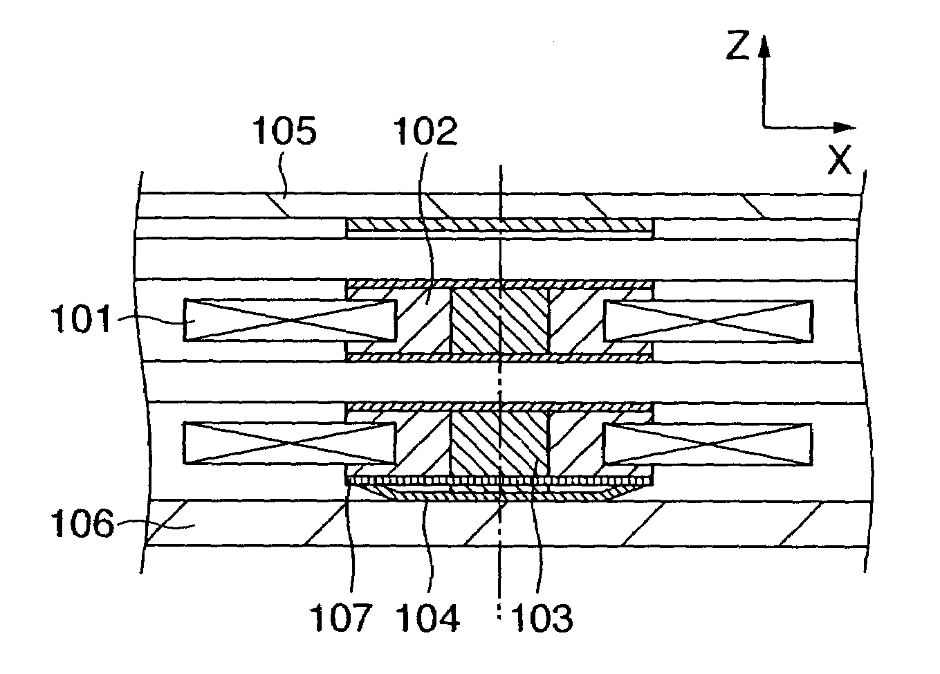
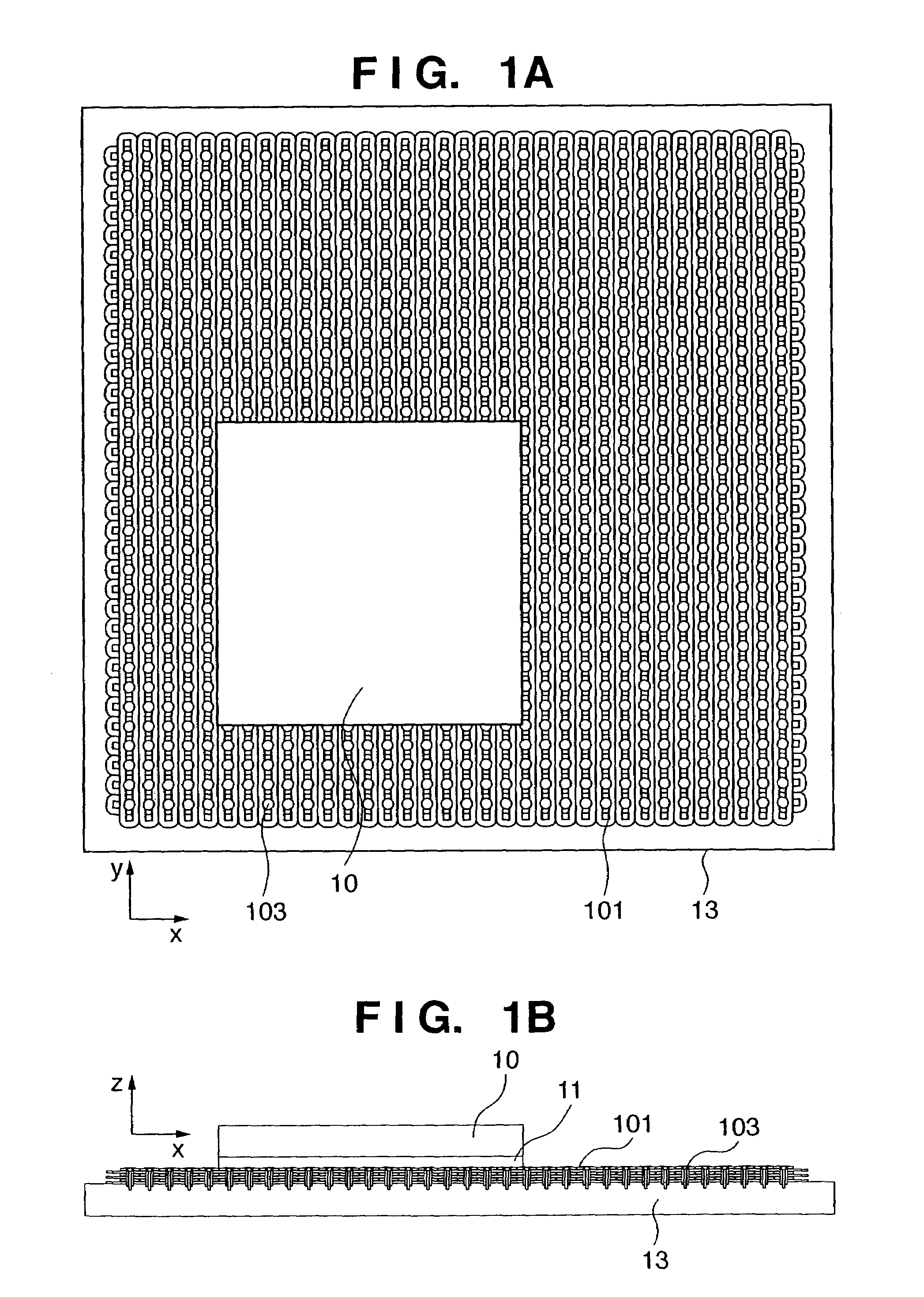
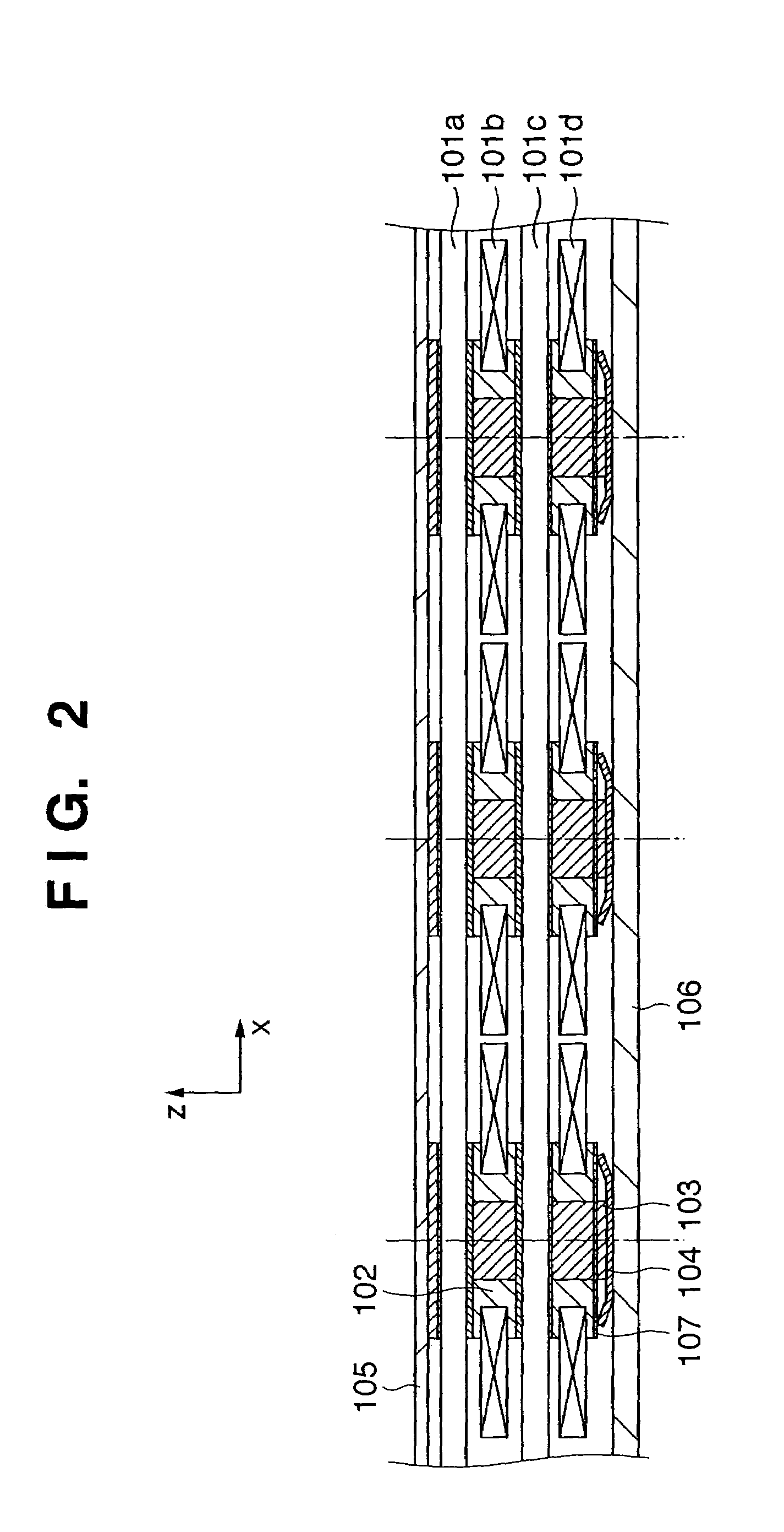
[0037]FIGS. 1A and 1B are views showing a plane motor according to the first embodiment of the present invention. FIG. 2 is a view showing a coil support unit in FIG. 1B. Since, in FIGS. 1A and 1B, a surface plate serving as a moving surface of a movable portion 10 is omitted for the sake of simplicity, a coil 101 is exposed. However, in an actual unit, the coil 101 is covered with a surface plate. The stage 10 serving as an object has a magnet portion 11, and can be driven in the X and Y directions by selectively causing a current to flow to the coil 101 on a base 13.
[0038]For example, on the first layer from the top (movable portion side), the coil 101 includes substantially elliptical coils 101a with an elliptical (long side) portion in an X direction, and the plurality of substantially elliptical coils 101a are juxtaposed in a Y direction. On the second layer, the coil 101 includes substantially elliptical coils 101b with an elliptical portion in a Y direction, and the plurality...
second embodiment
[0050]FIGS. 6A and 6B are views showing the second embodiment. FIG. 6A is an enlarged view of a coil support unit seen from a Y direction. FIG. 6B is a view of a coil having an elliptical portion in the Y direction (e.g., the coil on the second layer in FIG. 6A), seen from a Z direction. The detailed description of the similar arrangement of the first embodiment will be omitted. In the second embodiment, a spacer 102 does not abut against a rib 103 in the X direction and a major-axis direction (Y direction) of the thrust directions. Between the spacers 102 stacked in the Z direction, a shim 108 is arranged to abut against the rib in the X and Y directions.
[0051]When a cone disc spring 104 applies a preload force to generate the optimal friction between the spacer 102 and the shim 108, the spacer 102 can be constrained in the thrust direction. In this case, the preload force is set such that the friction is larger than the thrust of the coil 101, and smaller than the thermal expansio...
third embodiment
[0055]FIGS. 7A to 7E show the third embodiment. FIG. 7A is a view of a coil support unit seen from a Y direction. FIGS. 7B to 7E are views of a coil having an elliptical portion in the Y direction (e.g., the coil on the second layer in FIG. 7A), seen from a Z direction. A detailed description of the arrangement similar to the first embodiment will be omitted. As one characteristic of this embodiment, a coil can slide with a spacer in this embodiment, while the spacer can slide in a major-axis direction in the first and second embodiments. A leaf spring 202′ serving as an anisotropic spring is used to support a coil 201 to move the coil 201 only in one direction. The leaf spring 202′ is integrated with a spacer 202 between the coil 201 and a rib 203 serving as a coil support portion.
[0056]In this case, in consideration of efficiency, cone disc spring 204 applies a preload force to the spacer 202 in the Z direction to support the spacer 202, although the spacer 202 may be fixed to the...
PUM
| Property | Measurement | Unit |
|---|---|---|
| force | aaaaa | aaaaa |
| thermal expansion | aaaaa | aaaaa |
| frictional force | aaaaa | aaaaa |
Abstract
Description
Claims
Application Information
 - R&D
- Intellectual Property
- Life Sciences
- Materials
- Tech Scout
- Unparalleled Data Quality
- Higher Quality Content
- 60% Fewer Hallucinations
Browse by: Latest US Patents, China's latest patents, Technical Efficacy Thesaurus, Application Domain, Technology Topic, Popular Technical Reports.
© 2025 PatSnap. All rights reserved.Legal|Privacy policy|Modern Slavery Act Transparency Statement|Sitemap|About US| Contact US: help@patsnap.com


