Analytical instruments using a pseudorandom array of sources, such as a micro-machined mass spectrometer or monochromator

a technology of analytic instruments and sources, applied in the direction of particle separator tubes, simultaneous indication of multiple variables, amplifier modifications to reduce noise influence, etc., can solve the problem of proportionally reducing the signal at the detector, reducing the sample volume or intensity, and reducing the performance of the device to an unacceptable low level. , to achieve the effect of increasing the duty cycle, maximizing the signal, and improving the signal-to-noise ratio

Inactive Publication Date: 2008-03-04
UNIV OF WASHINGTON
View PDF34 Cites 80 Cited by
  • Summary
  • Abstract
  • Description
  • Claims
  • Application Information

AI Technical Summary

Benefits of technology

[0008]The signal-to-noise ratio determines the sensitivity of analytical instruments. It is therefore desirable to maximize the signal for a given level of detector noise. Multiplexing techniques, which allow an increased duty cycle for pulsed sources or the utilization of multiple sources in parallel, can improve the signal-to-noise ratio. Pseudorandom sequences have been previously used to increase the duty cycle of pulsed source in various instruments. In one aspect, novel methods and structures are disclosed herein which employ pseudorandom sequences to spatially arrange multiple sources in a pseudorandom source array. The pseudorandom source array can replace the single source in analytical instruments relying on spatial separation of the sample or the probe particles / waves emitted by the sources. The large number of sources in this pseudorandom source array enhances the signal on a position sensitive detector. A mathematical deconvolution process retrieves a spectrum with improved signal-to-noise ratio from the detector signal. The improved signal-to-noise ratio can allow dramatic improvements of the analytical instruments employing the pseudorandom source array. Most notably it allows the miniaturization of some instruments, a prerequisite for a wide array of new applications.

Problems solved by technology

Miniaturization of analytical instruments, which is highly desirable based on considerations such as cost and portability, often requires the circumvention of these scaling relations, since otherwise device performance is reduced to an unacceptable low level.
A prominent problem stemming from miniaturization is the reduction of sample volume or intensity, due to the smaller source, causing a proportionally reduced signal at the detector and thus a reduced signal-to-noise ratio, if the noise stems mainly from the detector, as is often the case.

Method used


Image

  • Analytical instruments using a pseudorandom array of sources, such as a micro-machined mass spectrometer or monochromator
  • Analytical instruments using a pseudorandom array of sources, such as a micro-machined mass spectrometer or monochromator
  • Analytical instruments using a pseudorandom array of sources, such as a micro-machined mass spectrometer or monochromator

Examples


embodiment

Mass Spectrometer Embodiment

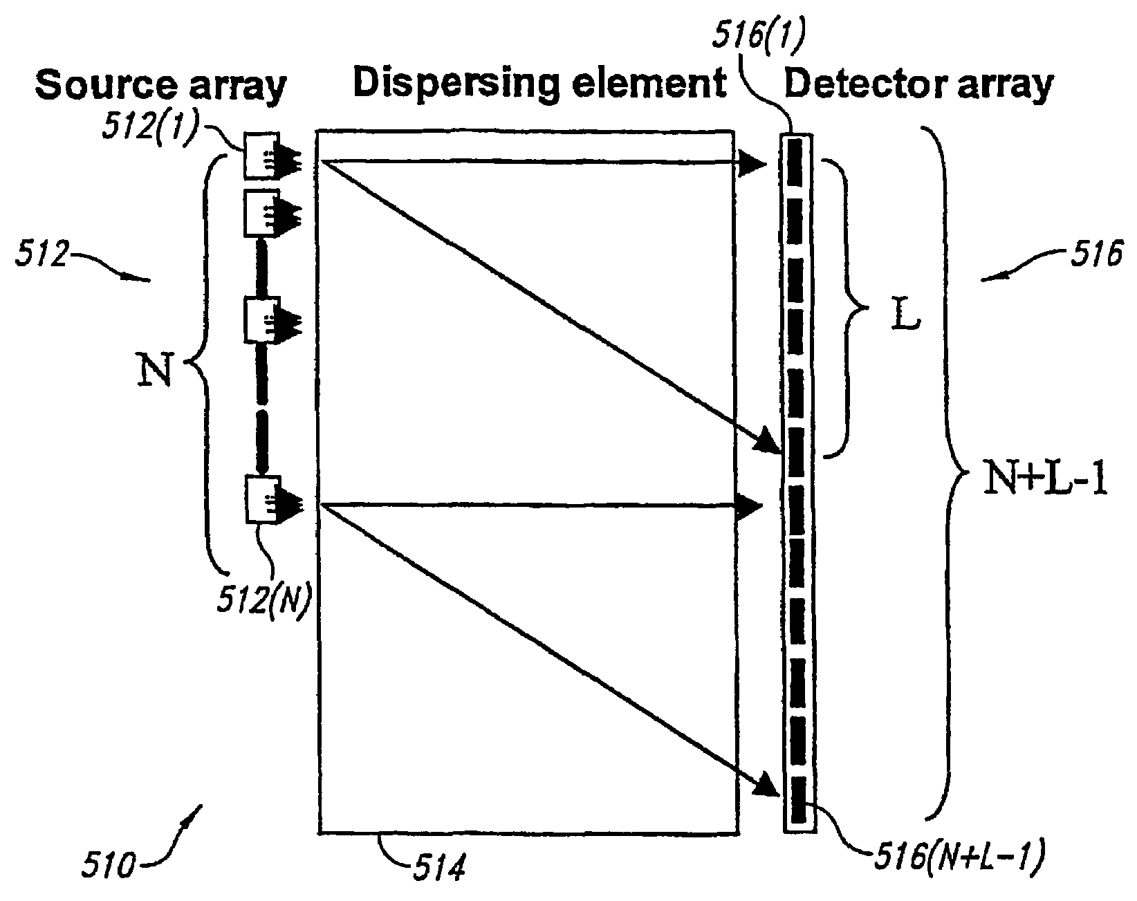
[0078]In one embodiment, a mass spectrometer (“MS”) embodies an assembly of (i) N ion sources, (ii) a mass separator and (iii) a detector array. The detector array has m*(N+L−1) units (m=1, 2, 4) depending on the overall MS lay-out, where L is the length of the mass spectrum (L<=N). A first embodiment takes the form of a non-scanning mass spectrometer, while a second embodiment takes the form of a scanning system. The MS has N=2n−1 subunits where n is an integer. The source array consists of emitting and non-emitting units, arranged in the so-called pseudorandom sequence. The non-emitting units may take the form of sources rendered temporarily or permanently incapable of emitting, or of blanks (i.e., space holders incapable of emitting in any situation). The source array can be made planar-linear, as illustrated in FIG. 5, but is not limited to this layout.

[0079]The detector can be any position sensitive particle detector, its effective spatial resolution...


PUM

PropertyMeasurementUnit
lengthaaaaaaaaaa
angleaaaaaaaaaa
pixel sizeaaaaaaaaaa

Abstract

Novel methods and structures are disclosed herein which employ pseudorandom sequences to spatially arrange multiple sources in a pseudorandom source array. The pseudorandom source array can replace the single source in analytical instruments relying on spatial separation of the sample or the probe particles / waves emitted by the sources. The large number of sources in this pseudorandom source array enhances the signal on a position sensitive detector. A mathematical deconvolution process retrieves a spectrum with improved signal-to-noise ratio from the detector signal.

Description

CROSS-REFERENCE TO RELATED APPLICATIONS[0001]This application is a 371 of PCT / US03 / 05517, filed Feb. 20, 2003 and claims the benefit of U.S. Provisional Patent Application No. 60 / 358,124, filed Feb. 20, 2002, each of which are incorporated by reference in its entirety herein.STATEMENT REGARDING FEDERALLY SPONSORED RESEARCH[0002]This invention was made with U.S. Government support under National Science Foundation Grant No. BIR-9214821. The United States government may have certain rights in this invention.BACKGROUND OF THE INVENTION[0003]Analytical instruments are useful in performing research, testing, diagnostics and other types of work. Analytical instruments 10 may operate in the space domain as illustrated in FIG. 1A, or in the time domain as illustrated in FIG. 1B.[0004]As illustrated in FIGS. 1A and 1B, analytical instruments 10 typically employ three fundamental components: a source 12, a disperser 14; and a detector 16. The source 12 typically takes one of two forms: i) emi...

Claims


Application Information

Patent Timeline
Patent Type & Authority Patents(United States)
IPC IPC(8): G01S3/04G01S3/801G01S3/781G01S3/86G01N37/00G06F19/00H01JH01J1/00H01J49/00H01J49/10H01J49/40H04K1/00
CPCH01J49/107
Inventor SCHEIDEMANN, ADIHESS, HENRY
Owner UNIV OF WASHINGTON
Why Eureka
Try Eureka