

Particle beam processing apparatus and materials treatable using the apparatus
a technology of particle beam and processing equipment, which is applied in the field of particle beam processing equipment and materials treatable using such equipment, can solve the problems of increasing the seal initiation temperature, affecting the sealing effect of the film, and the current technology cannot be used in certain industries,
- Summary
- Abstract
- Description
- Claims
- Application Information
AI Technical Summary
Benefits of technology
Problems solved by technology
Method used
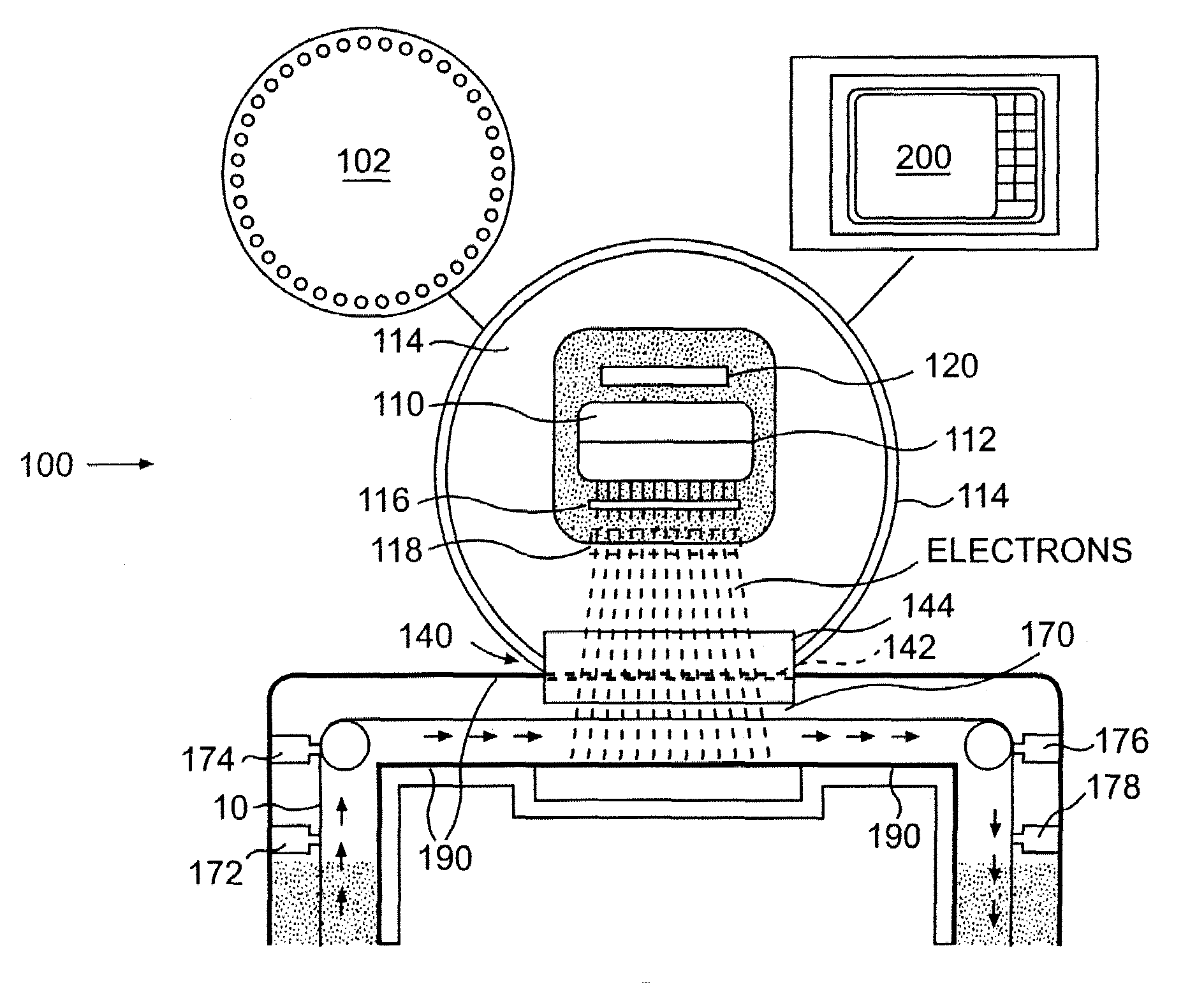
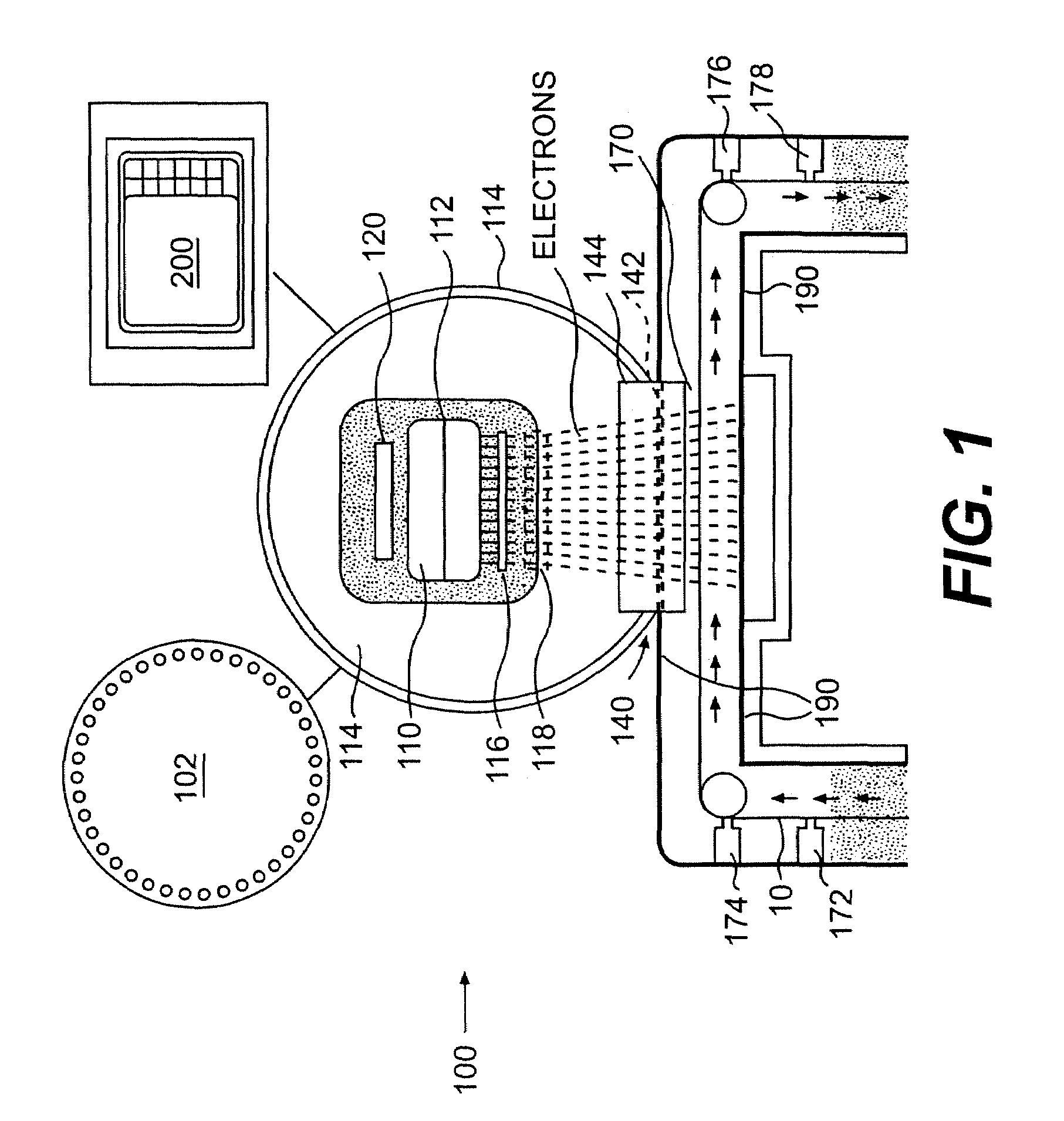
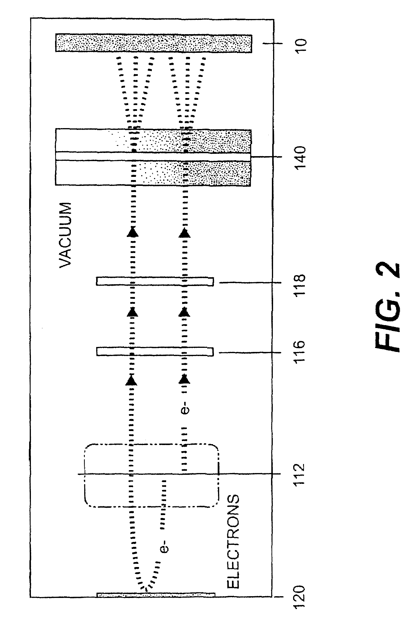
Image

Examples
example 1
[0062]The result of a first experiment, shown in FIG. 4, indicates that particle beam processing device 100 using thin foil 142 that is made of titanium having a thickness of less than 12.5 micrometer improves the electron penetration in substrate 10.
[0063]In the first experiment, thin film nylon dosimeters were used to measure the penetration capability of electrons. The parameters for this experiment include: a constant operating voltage of 90 kVolts, a dose of 5 Mrads, and a thin titanium foil. Three specimens were tested to study three different titanium foil thicknesses of 12.5, 8, and 5 micrometers, one for each foil thickness.
[0064]The three specimens were made of thirty dosimeters, each having a surface area of approximately 2×2 cm2. These dosimeters were divided into three stacks, each stack containing an arrangement of ten dosimeters one on top of the other. One edge of each stack of dosimeters was taped to a polyester carrier having a thickness of 125 micrometer. The thre...
example 2
[0066]The result of a second experiment, shown in FIG. 5, indicates that thinner foil not only improves electron penetration on a substrate, but also increases the efficiency or machine yield K.
[0067]In the second experiment, similar to the first experiment, thin film nylon dosimeters were used to measure the machine yield K of a processing device having a width of 1.5 feet at various operating voltages measured in kVolts. Four measurements were run to study four different titanium foils having thicknesses of 12.5, 10, 8, and 5 micrometers.
[0068]The value of machine yield K was obtained by calculating the average of nine individual dosimeter chips. Each dosimeter of 2×2 cm2 was taped on one edge to a polyester carrier. Each polyester carrier contained nine dosimeters. The polyester carrier was taped to the paper substrate and fed through processing device 100 to receive radiation treatment. After irradiation the dosimeters were annealed at 60° C. for 5 minutes. Thereafter, the optic...
example 3
[0074]The result of a third experiment, as shown in FIG. 6, illustrates one advantage of operating processing device 100 at a voltage of 110 kVolts or less in the field of Flexible Food Packaging.
[0075]In the third experiment, depth dose profiles for processing device 100 at various operating voltages were measured according to the procedure described earlier with respect to the first experiment. A typical application of flexible food packaging is the packaging for processed meat and cheese which commonly include three layers top film, adhesive, and sealant. For example, Table 1 below provides a typical packaging layers and their normalized thicknesses, measured in grams / m2:
[0076]
TABLE 1Top film of 0.5 mil polyester type (PET):17.0 gram / m2Adhesive: 3.0 gram / m2Sealant of polyethylene copolymer:40.0 gram / m2
Electron beam has generally been used to cure the adhesive in between the top film and the sealant.
[0077]As illustrated in FIG. 6, EB processing device currently available in the ma...
PUM
| Property | Measurement | Unit |
|---|---|---|
| thickness | aaaaa | aaaaa |
| thickness | aaaaa | aaaaa |
| thickness | aaaaa | aaaaa |
Abstract
Description
Claims
Application Information