
Voltage, temperature, and process independent programmable phase shift for PLL

Inactive Publication Date: 2008-04-15
ALTERA CORP
View PDF34 Cites 8 Cited by
  • Summary
  • Abstract
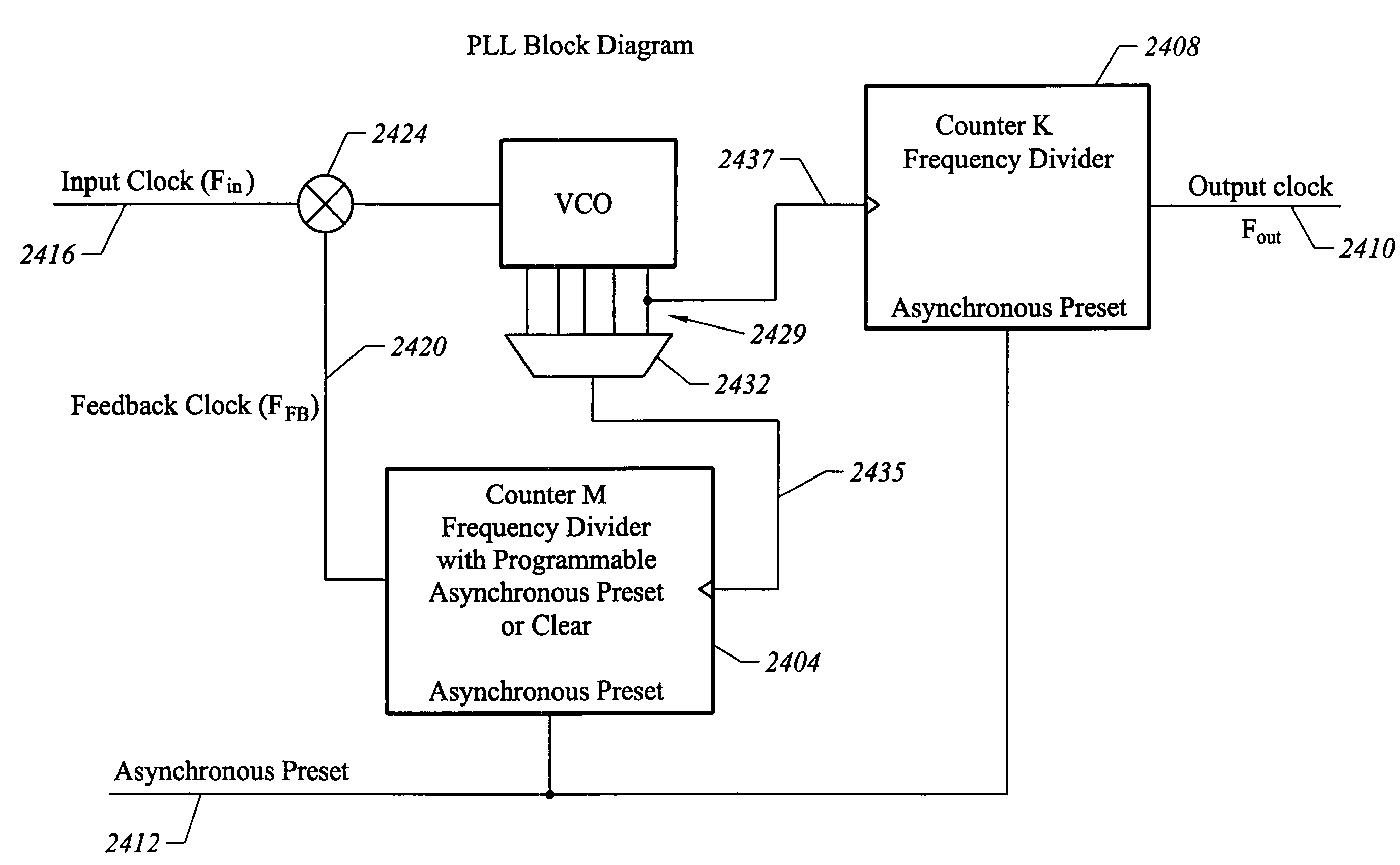
  • Description
  • Claims
  • Application Information

AI Technical Summary

Benefits of technology

[0006]The invention provides a programmable phase shift feature for a phase locked loop (PLL) or delay locked loop (DLL) circuit. The phase shift may be adjusted with equal steps. Each step may be a fixed percentage of the clock period, and will be independent of supply voltage, temperature, and process parameters. Having an on-chip PLL or DLL is an important feature in programmable logic devices (PLDs). Users can use a PLL to improve circuit performance and generate clocks with different frequencies. The phase requirement for the output clock varies depending on the application. A very useful feature for users is the ability to tune the phase of the output clock, and for the result to be independent of process, temperature, and power supply.
[0007]In an embodiment, a voltage controlled oscillator (VCO) is implemented using a ring oscillator with approximately equal delay for each stage. Other circuit implementations for a VCO may also be used, including those well known to one of skill in the art. The delay is controlled by the voltage from charge pump The number of stages in the VCO is programmable. This programmability allows a wider frequency range for the VCO. As a higher frequency as specified, a fewer number of stages are needed.

Problems solved by technology

Under some circumstances, such as when there is a wide frequency difference between the two clock, the locking time may be slow.
A slower locking time is undesirable because it will take longer for the system to initialize before normal operation.
Also, as the master clock varies, it will take longer for the clock synchronization circuit to track these variations.

Method used


Image

  • Voltage, temperature, and process independent programmable phase shift for PLL
  • Voltage, temperature, and process independent programmable phase shift for PLL
  • Voltage, temperature, and process independent programmable phase shift for PLL

Examples


Embodiment Construction

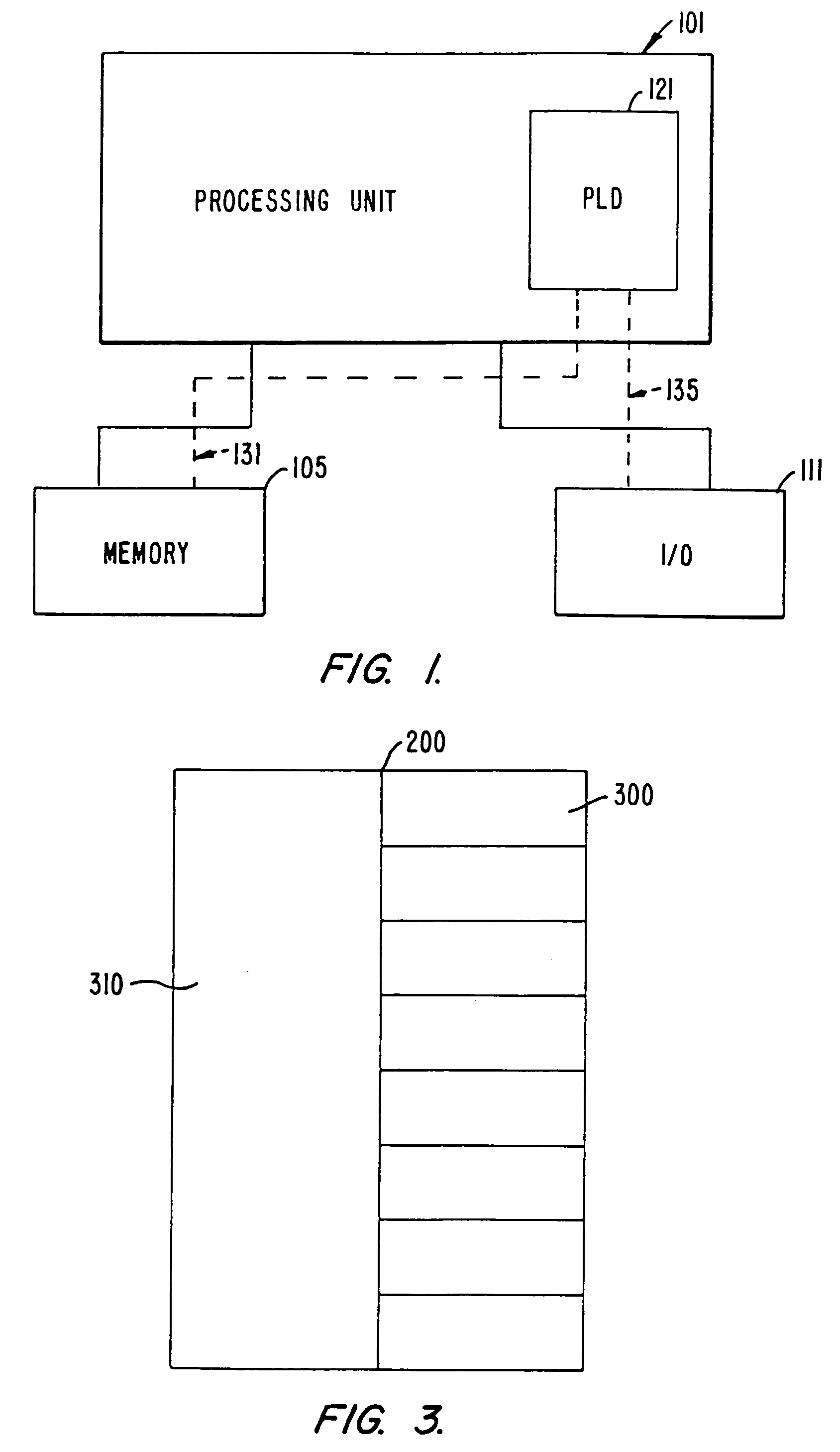
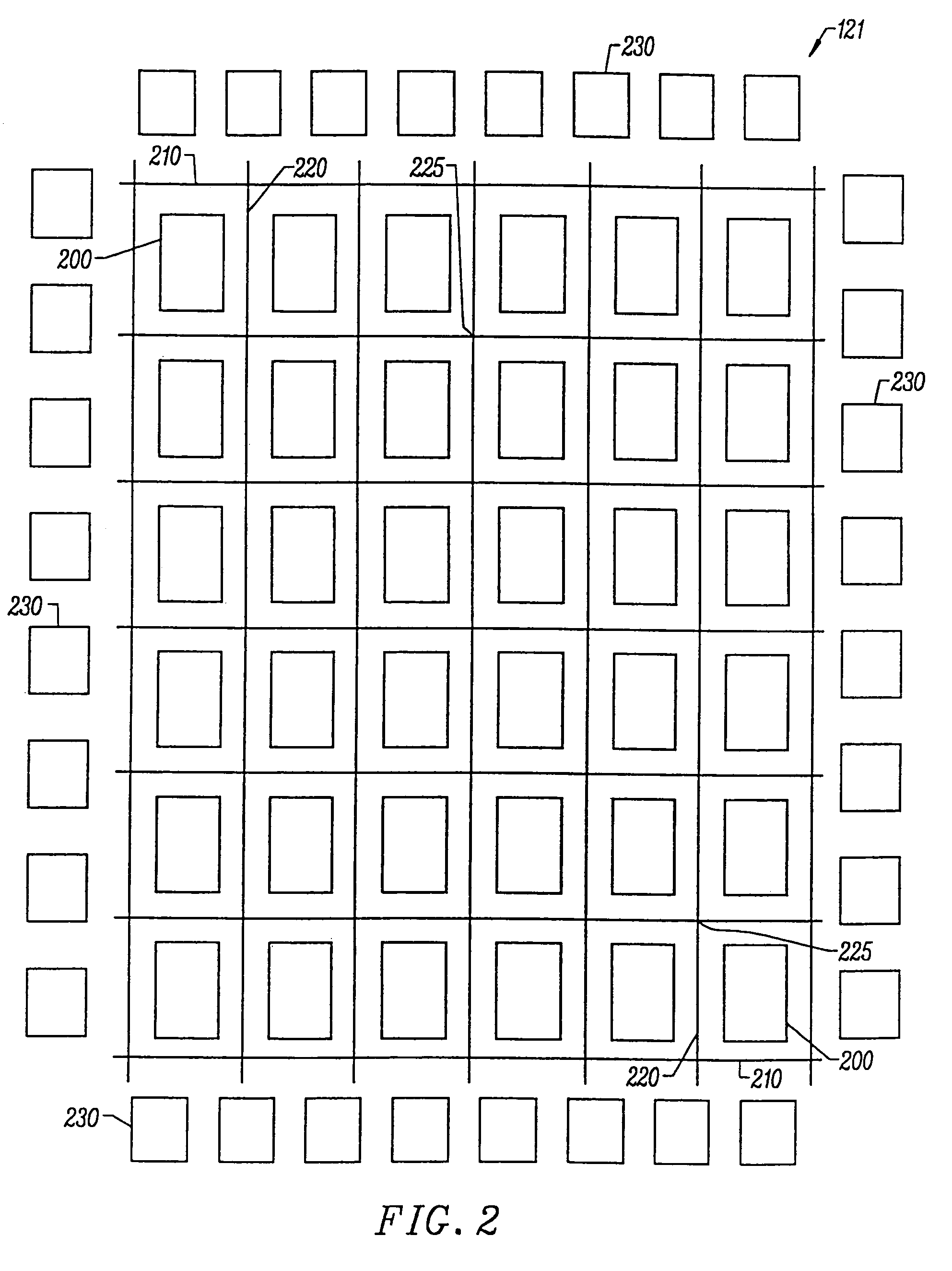
[0042]FIG. 1 shows a block diagram of a digital system within which the present invention may be embodied. The system may be provided on a single board, on multiple boards, or even within multiple enclosures. FIG. 1 illustrates a system 101 in which a programmable logic device 121 may be utilized. Programmable logic devices are sometimes referred to as a PALs, PLAs, FPLAs, PLDs, CPLDs, EPLDs, EEPLDs, LCAs, or FPGAs and are well-known integrated circuits that provide the advantages of fixed integrated circuits with the flexibility of custom integrated circuits. Such devices allow a user to electrically program standard, off-the-shelf logic elements to meet a user's specific needs. See, for example, U.S. Pat. No. 4,617,479, incorporated by reference for all purposes. Programmable logic devices are currently represented by, for example, Altera's MAX®, FLEX®, and APEX™ series of PLDs. These are described in, for example, U.S. Pat. Nos. 4,871,930, 5,241,224, 5,258,668, 5,260,610, 5,260,6...


PUM


Abstract

A circuit provides a programmable phase shift feature, where the phase shift is programmably selectable by a user. This circuitry may be incorporated in a programmable logic device (PLD) or field programmable gate array (FPGA) to provide additional programmability features. The programmable phase shift circuitry may be implemented within a phase locked loop (PLL) or delay locked loop (DLL) circuit. In an implementation, the programmable phase shift circuitry is implemented using two programmable counters.

Description

[0001]This application is a continuation of U.S. patent application Ser. No. 09 / 731,473, filed Dec. 5, 2000, now U.S. Pat. No. 6,642,758, which is a continuation-in-part of U.S. patent application Ser. No. 09 / 432,142, filed Nov. 2, 1999, now U.S. Pat. No. 6,369,624, which claims the benefit of U.S. provisional applications 60 / 169,161, filed Dec. 6, 1999; 60 / 106,876, filed Nov. 3, 1998; 60 / 107,101, filed Nov. 4, 1998; and 60 / 107,166, filed Nov. 5, 1998, and also claims the benefit of U.S. provisional application 60 / 169,161, filed Dec. 6, 1999, which are incorporated by reference along with all references cited in this application.BACKGROUND OF THE INVENTION[0002]The present invention relates to the field of electronic circuits, and in particular, programmable phase shift circuitry.[0003]Many electronic systems use a master clock signal to synchronize the operation of all the circuitry and integrated circuit. A fundamental concept in electronic design, synchronous operation is importa...

Claims


Application Information

Patent Timeline
IPC IPC(8): H03L7/095H03K5/00H03K19/177H03K23/66H03L7/081H03L7/089H03L7/099H03L7/183
CPCH03F1/301H03H11/245H03K19/1774H03K23/665H03L7/081H03L7/089H03L7/0891H03L7/0996H03L7/0997H03L7/18H03L7/183H03K2005/00045
Inventor WANG, BONNIE I.HUANG, JOSEPHSUNG, CHIAKANGWANG, XIAOBAOKIM, IN WHANYEUNG, WAYNENGUYEN, KHAI
Owner ALTERA CORP
Learn More