
Long term ambulatory intra-aortic balloon pump with three dimensional tortuous shape

a three-dimensional, tortuous technology, applied in the field of intra-aortic balloon pumps, can solve the problems of premature failure, undesirable insertion location, and relative limited level of cardiac assistance, and achieve the effects of reducing the overall diameter of the device, and facilitating minimally invasive surgical implantation

Active Publication Date: 2008-05-20
L VAD TECH
View PDF46 Cites 61 Cited by
  • Summary
  • Abstract
  • Description
  • Claims
  • Application Information

AI Technical Summary

Benefits of technology

[0014]The CARDIOVAD® device was optimized for permanent (i.e. months up to years) implantation, while the catheter-based temporary intra-aortic balloon pump was optimized for simple insertion in anticipation of short term use (i.e. hours up to days). The present invention is a variant of the CARDIOVAD® permanent balloon pump device, and the temporary intra-aortic balloon pump to retain the advantages of both systems, while eliminating some of the disadvantages. The present invention, referred to herein as a long term intra-aortic balloon pump (LTIABP), is intended for prolonged use (i.e. weeks up to years) for ambulatory patients, and retains the advantages of permanent implantation while simplifying the surgical implantation technique in a fashion reminiscent of the temporary intra-aortic balloon pump (IABP). The present invention modifies the structural configuration of the temporary intra-aortic balloon pump in order to allow use as a long term intra-aortic balloon pump. The first modification according to the present invention is to increase the stroke volume for more clinical effectiveness in ambulatory patients by providing a large volume (i.e. 50 cubic centimeters (cc) to 65 cubic centimeters (cc), inclusive) displacement blood pump, and by providing an increased cross sectional area for the power conduit to permit the use of alternative pumping mediums, preferably compressed air or any other gas, such as helium. A second modification according to the present invention is at the skin entrance of the power / signal conduit with a PAD.
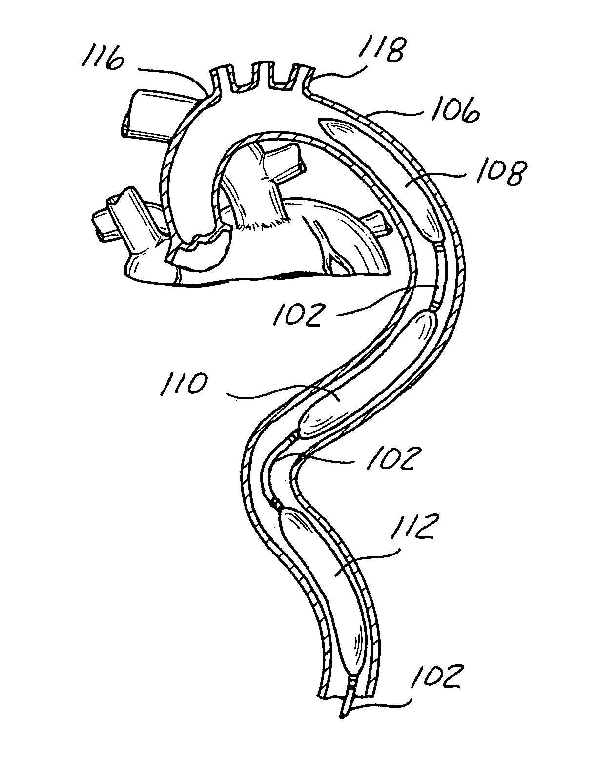
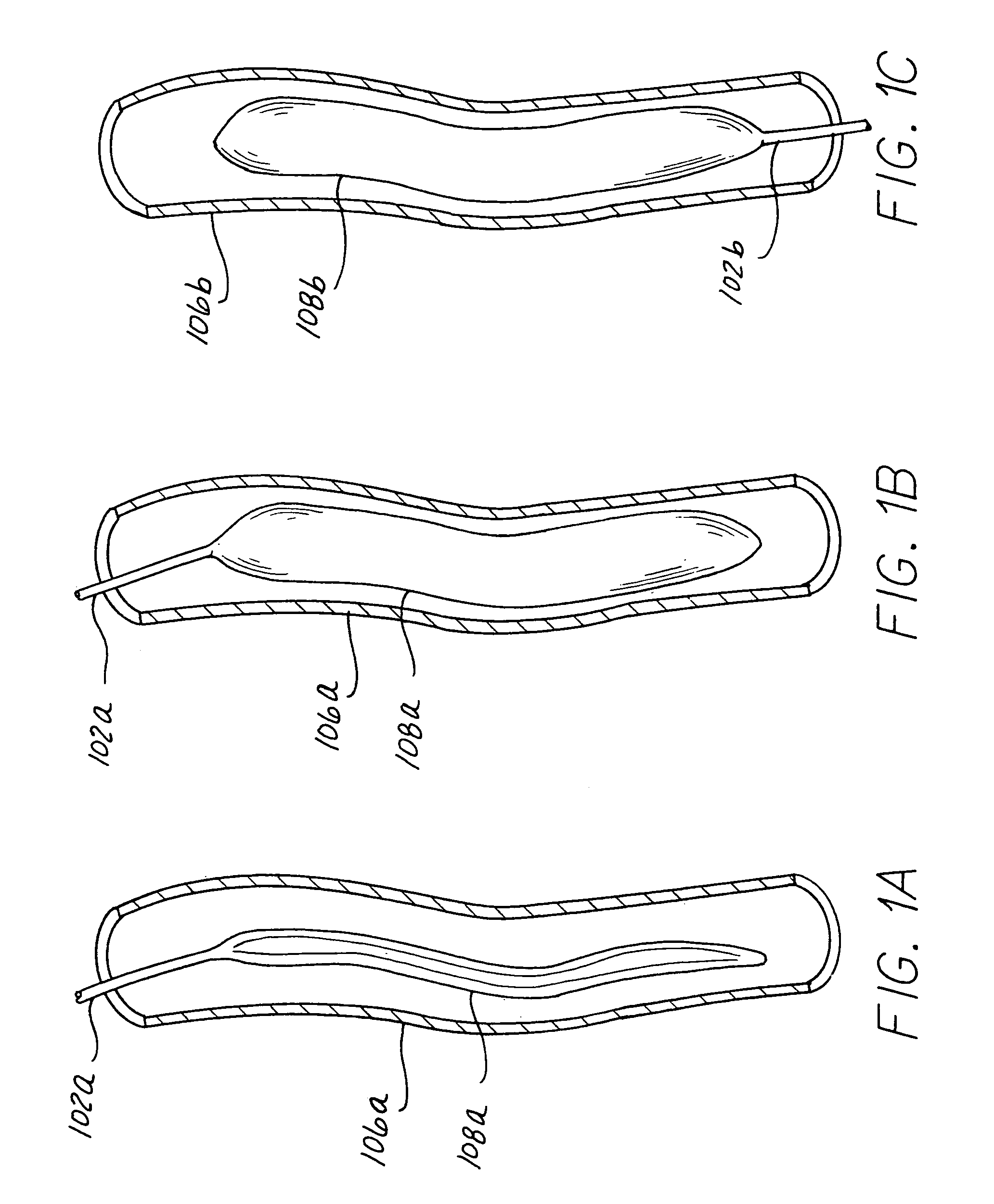
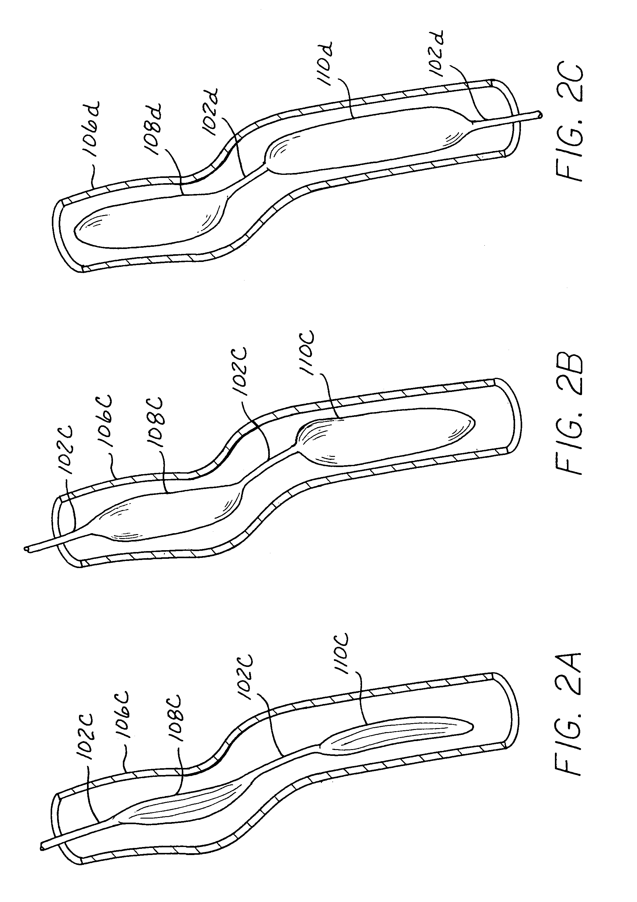
[0016]An aortic blood pump according to the present invention can assist cardiac function during a cardiac cycle of a patient when positioned with respect to an aorta of the patient. The aortic blood pump can include an elongate semi-rigid shell having a contoured, concave inner surface terminating at a peripheral side edge. A flexible membrane can be continuously bonded to the shell adjacent the peripheral side edge to define an enclosed inflatable chamber. At least one passage can extend through the shell into communication with the inflatable chamber to inflate and deflate the chamber. A stent can be partially embedded in the shell and / or can be connected to the outer surface of the semi-rigid shell to extend outwardly from the shell to define a substantially open cylindrical area for expansion of the flexible membrane when inflated. The stent can be movable between an expanded position and a retracted position. The retracted position of the stent can reduce the overall diameter of the device to facilitate minimally invasive surgical implantation. When properly positioned within the aorta, the stent can be expanded to define the substantially open cylindrical area encompassing the zone of inflation of the flexible membrane within the aorta.
[0017]An inflatable balloon pump can also be supported by being suspended within a central portion of a collapsed or retracted stent for minimally invasive surgical positioning with respect to the aorta of the patient. After expansion of the stent in an endoscopically selected location of the aorta, the inflatable balloon pump can be cyclically inflated and deflated to assist the cardiac function based on measured clinical parameters of the patient.

Problems solved by technology

However, this relatively limited level of cardiac assistance is insufficient, and the typical location of insertion is undesirable, for ambulatory patients.
The furling and wrapping of the material raises concerns regarding damage to the material of the balloon pump which might possibly lead to premature failure when subjected to numerous pumping cycles, if prolonged use over a period greater than a few days is mandated for a particular patient.
The use of a helium pumping medium may not be as practical as the use of an air pumping medium in order to provide a simple cardiac assistance device for long term ambulatory patients.
Distal ischemic complications are a concern in many of these methods.
However, this patent does not recognize or address the potential tortuosity of the aorta that typically can occur in patients, where the aorta is not smooth and uniform in a two-dimensional plane as depicted in medical books, but rather twists and turns through three-dimensional space within the body cavity creating greater difficulty in properly positioning and operating a balloon pump within the descending aorta of the patient.
The patent does not address the potential clinical danger of stroke created by a catheter moving across the entrances to the arch vessels (e.g. the left subclavian artery, the left common carotid artery, and the innominate artery).
The clinical danger of stroke, by way of example and not limitation, can be linked to: (1) risk of dislodgment of embolus or plaque into the arch vessels during insertion of the balloon pump around the arch into the ascending aorta; (2) risk of occlusion of the arch vessels; (3) risk of repeated abrading action against the surface of the arch and entrance to the arch vessels; and (4) risk of dislodgment of embolus or plaque during withdrawal or replacement of the balloon pump.
Each of these patents teaches the desirability of a temporal sequence of inflation and / or deflation, even though such procedures are of undetermined effectiveness and accordingly are not well established as providing the amount of assistance desired for an ambulatory patient.

Method used


Image

  • Long term ambulatory intra-aortic balloon pump with three dimensional tortuous shape
  • Long term ambulatory intra-aortic balloon pump with three dimensional tortuous shape
  • Long term ambulatory intra-aortic balloon pump with three dimensional tortuous shape

Examples


Embodiment Construction

[0048]Various embodiments are shown throughout the Figures illustrating the present invention, and include common elements in different structural configurations where common elements are designated with a common base numeral and differentiated with a different alphabetic designation for the various embodiments. Descriptions for the base numeral designations are considered to be generic to the different alphabetic extensions added to the alternative embodiments except as specifically noted herein.

[0049]The present invention provides a pumping chamber lying completely within the lumen of the aorta rather than being embedded or implanted in the wall of the aorta. By way of example and not limitation, a surgeon can anastomose a length of vascular graft end-to-side directly to the aorta and use this graft as the aortic cannulation point. The vascular graft can be long enough to reach the subcutaneous skin layer, thereby simplifying exchange of the LTIABP if exchange becomes necessary du...


PUM


Abstract

An inflatable balloon pump can be anchored with respect to a wall of the aorta for endoscopic surgical positioning with respect to the aorta of the patient. After engagement of the anchor member in an endoscopically selected location of the aorta, the inflatable balloon pump can be cyclically inflated and deflated to assist the cardiac function based on measured clinical parameters of the patient. The balloon pump can include tapered longitudinal ends and / or be segmented into a plurality of pumping chamber subsegments, each pumping chamber subsegment separated by a flexible power conduit link, where the diameter of the pumping chamber subsegments are independent of one another. Anchor members can be provided located adjacent at least one longitudinal end of the pump, or each longitudinal end of each inflatable chamber defining the pump, or sheathing at least one of the inflatable chambers defining the pump.

Description

CROSS-REFERENCE TO RELATED APPLICATIONS[0001]This application is a continuation-in-part of U.S. patent application Ser. No. 10 / 746,543 filed Dec. 24, 2003, and claims the benefit of U.S. provisional patent application Ser. No. 60 / 477,704 filed Jun. 11, 2003, both of which are incorporated by reference herein in their entirety.FIELD OF THE INVENTION[0002]The present invention relates to an intra-aortic balloon pump having at least one anchor member, and more particularly to an intra-aortic balloon pump for long term ambulatory use while being anchored in a desired location within the descending aorta of a patient.BACKGROUND OF THE INVENTION[0003]An aortic blood pump can be permanently surgically implanted in the wall of the aorta to augment the pumping action of the heart. The aortic blood pump is sometimes referred to as a mechanical auxiliary ventricle assist device, dynamic aortic patch, or permanent balloon pump. Alternatively, the aortic blood pump can be inserted using minimall...

Claims


Application Information

Patent Timeline
Patent Type & Authority Patents(United States)
IPC IPC(8): A61N1/362A61M60/139A61M60/295A61M60/497A61M60/843A61M60/871
CPCA61M1/1072A61M2230/04A61M60/274A61M60/497A61M60/139A61M60/295A61M60/843
Inventor KANTROWITZ, ALLEN B.
Owner L VAD TECH
Learn More