Methods of fabricating complex blade geometries from silicon wafers and strengthening blade geometries

a technology of complex blade geometries and silicon wafers, applied in the field of ophthalmic, microsurgical and nonsurgical blades and mechanical devices, can solve the problems of inability to achieve superior sharpness consistency. achieve excellent control of the preformed bevel angle, increase the effect of mechanical device strength

Active Publication Date: 2008-07-08
BEAVER VISITEC INT US
View PDF163 Cites 23 Cited by
  • Summary
  • Abstract
  • Description
  • Claims
  • Application Information

AI Technical Summary

Benefits of technology

[0013]The above described disadvantages are overcome and a number of advantages are realized by the present invention which relates to a system and method for the manufacturing of surgical blades from a crystalline or poly-crystalline material, such as silicon, which provides for the machining of trenches in a crystalline or poly-crystalline wafer, by various means, at any desired bevel angle or blade configuration. The machined crystalline or poly-crystalline wafers are then immersed in an isotropic etching solution which uniformly removes layer after layer of molecules of the wafer material, in order to form a cutting edge of uniform radius, and of sufficient quality for soft tissue surgery applications. The system and method of the invention provides a very inexpensive means for the manufacture of such high quality surgical blades.
[0018]It is still another object of the invention to provide a system and method for increasing the strength of mechanical devices and surgical and non-surgical blades manufactured from single or poly-crystalline materials, including silicon, according to one or more of the processes described herein.
[0019]It is therefore an object of the present invention to provide a method based on an isotropic and an anisotropic etching methods that has none of the prior art deficiencies, and all the advantages discussed herein. This method allows complex blade geometries to be formed including, but not limited to, single and double bevel varieties of slit knives, trapezoidal knives, chisel knives among others. The aforementioned methods of manufacturing blades using the isotropic etching process according to several embodiments of the present invention are constrained by the availability of accurate mechanical methods to form the V-grooves that will eventually become the cutting edges of the blades. The method according to an embodiment of the present invention creates the V-grooves without adding any mechanical stresses to the wafer. By using a combination of photomasking, wet etching (isotropic and anisotropic) and dry etching (isotropic and anisotropic, including reactive ion etching) the V-grooves can be formed in an unlimited number of two-dimensional geometries and with excellent control over the preformed bevel angle. Once the initial V-grooves (or trenches) have been formed, the trenched wafers are then subjected to maskless wet isotropic etching process described herein. A final blade geometry and ultra sharp cutting edges can then be created.

Problems solved by technology

The greatest disadvantage of these processes is that the edge quality is variable, such that achieving superior sharpness consistency is still a challenge.
This is primarily due to the inherent limitations of the process itself.
The disadvantage of this method is that the sharpness consistency is still less than that achieved by the diamond blade manufacturing process.
Most high-volume surgeons will use diamond blades since the ultimate sharpness and sharpness variability of metal blades is inferior to that of diamond.
The disadvantage of this process is that it is slow and as a direct result, the cost to manufacture such diamond blades ranges from $500 to $5000.
However, while less expensive than diamonds, ruby and / or sapphire surgical quality blades still suffer from the disadvantage that the cost of manufacture is relatively high, ranging from $50 to $500, and their edges only last through about two hundred cases.
Therefore, these blades are sold for reuse and limited reuse applications.
However, in one form or another, these processes are limited in their ability to manufacture blades in various configurations and at a disposable cost.
However, due to the nature of the process, it is limited by the blade shapes and included bevel angles that can be attained.
This creates a blade with an included bevel angle of 54.7°, which has been found to be clinically unacceptable in most surgical applications as too obtuse.
This application is even worse when this technique is applied to making double bevel blades, for the included bevel angle is 109.4°.
The process is further limited to the blade profiles that it can produce.
In the methods described in greater detail below for manufacturing surgical and non-surgical blades and other mechanical devices from silicon, it is possible that mechanical damage can be induced into the brittle silicon material during one or more of the machining steps.
These points serve to initiate catastrophic failure of mechanical devices when they are loaded or stressed.
This is both inefficient and ineffective for volume production of high quality, defect free ophthalmic blades.
It is inefficient because it adds steps to the manufacturing process.
There are also significant cutting edge geometry constraints inherent to this process.
The bevel created by this process is limited to an inefficient 45° for a single bevel blade and an impractical 90° for a double bevel blade.
Further, the width of the bevel is severely constrained by the process to a maximum of one times the thickness of the wafer for a single bevel blade and one-half the thickness of the wafer for a double bevel blade.
These geometries result in a poor cutting tool as evidenced by a lack of adoption in the ophthalmic community.

Method used


Image

  • Methods of fabricating complex blade geometries from silicon wafers and strengthening blade geometries
  • Methods of fabricating complex blade geometries from silicon wafers and strengthening blade geometries
  • Methods of fabricating complex blade geometries from silicon wafers and strengthening blade geometries

Examples


first embodiment

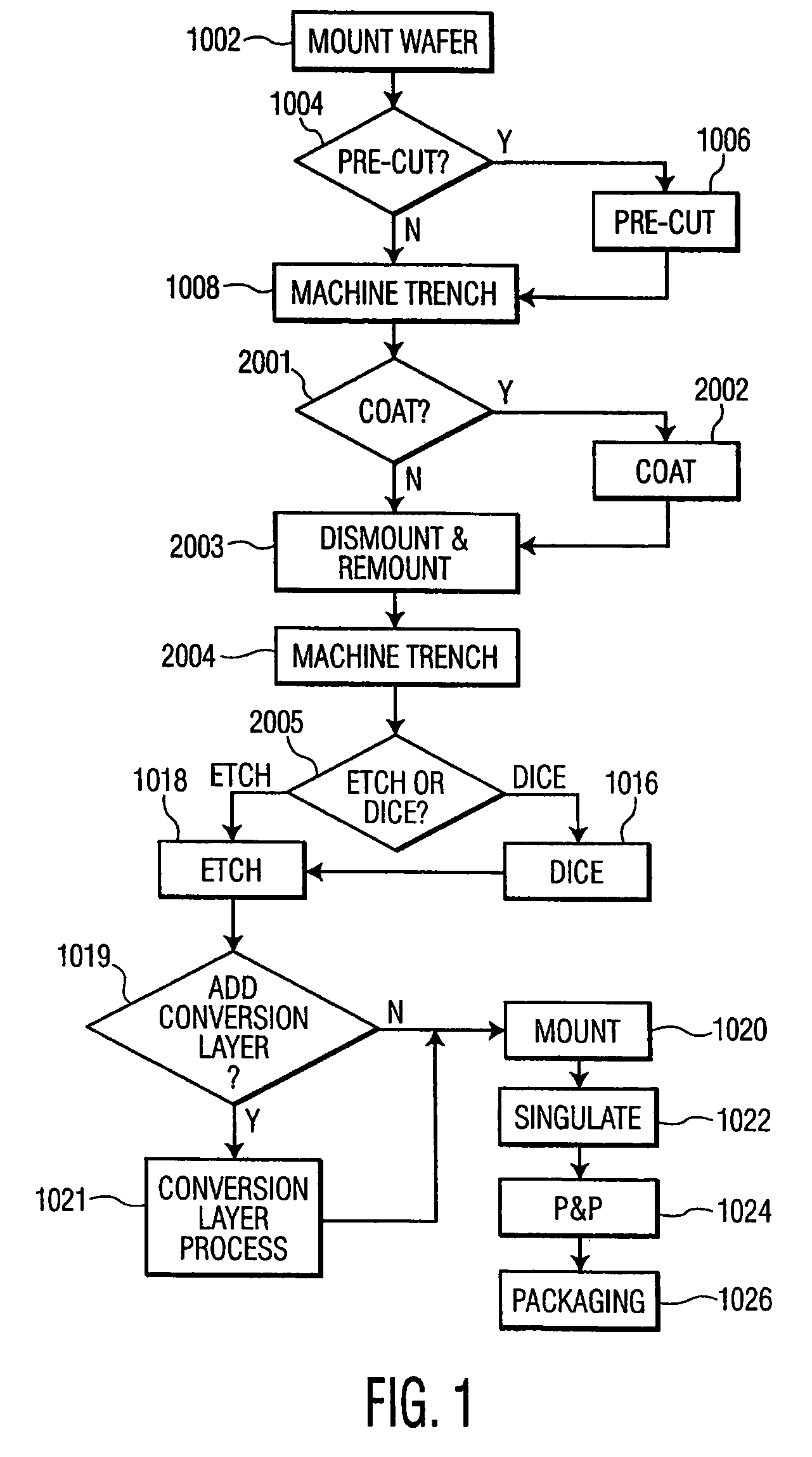
[0079]FIG. 1 illustrates a flow diagram of a method for manufacturing a double bevel surgical blade from silicon according to the present invention. The method of FIGS. 1, 2 and 3 generally describes processes which can be used to manufacture silicon surgical blades according to the present invention. However, the order of the steps of the method illustrated in FIGS. 1, 2 and 3 can be varied to create silicon surgical blades of different criteria, or to meet different manufacturing environments.

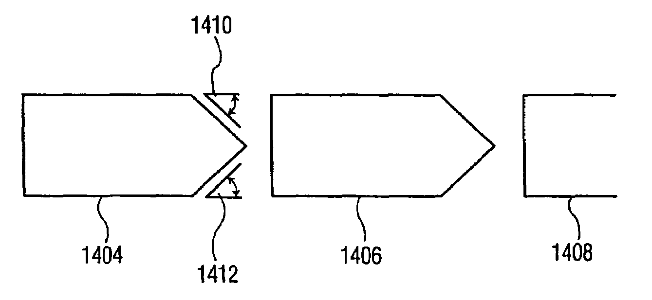
[0080]For example, although FIG. 1, as shown and described below, illustrates a method for manufacturing a double bevel blade in accordance with a first embodiment of the invention, this method can be utilized to manufacture multiple (i.e., three or more) facets per cutting edge. FIGS. 31A-C illustrate such a blade, and is described in greater detail below. Furthermore, the method as shown and described can also be utilized to manufacture a variable double bevel blade, as shown in FIG. 32. FI...

second embodiment

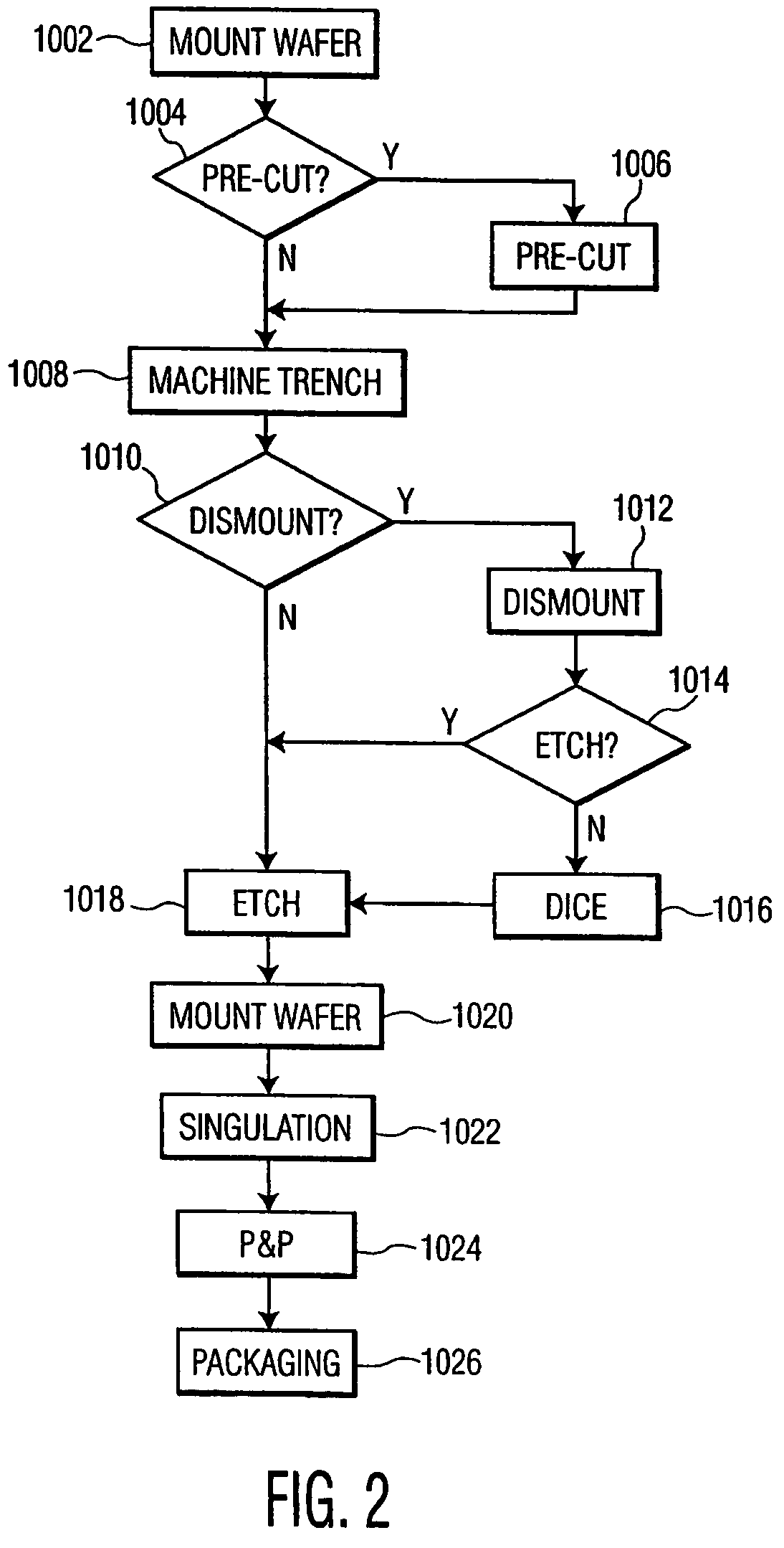
[0129]Having described the manufacturing process for a double bevel silicon-based surgical blade, attention is turned to FIG. 2, which illustrates a flow diagram of a method for manufacturing a single bevel surgical blade from silicon according to the present invention. Steps 1002, 1004, 1006, 1008 of FIG. 1 are the same for the method illustrated in FIG. 2, and therefore will not be repeated. However, the method for manufacturing a single bevel surgical blade differs in the next step, step 1010, from the method for manufacturing a double bevel blade, and therefore, will be discussed in detail.

[0130]Following step 1008 decision step 1010 determines whether the machined silicon wafer 202 will be dismounted from silicon wafer mounting assembly 204. If the single trench silicon wafers 202 were to be dismounted (in step 1012), then a further option is to dice the single trench wafers in step 1016. In optional dismounting step 1012, the silicon wafer 202 is dismounted from tape 308 utili...

third embodiment

[0132]FIG. 3 illustrates a flow diagram of an alternative method for manufacturing a single bevel surgical blade from silicon according to the present invention. The method illustrated in FIG. 3 is identical to that illustrated in FIG. 2, through steps 1002, 1004, 1006, 1008. After step 1008 in FIG. 3, however, there is coating step 2002. The coating step 2002 was described above in reference to FIG. 1, and need not be discussed in detail again. The result of the coating step is the same as was described previously: the machined side of silicon wafer 202 has a layer 1102 over it.

[0133]Following the coating step 2002, the silicon wafer 202 is dismounted and remounted in step 2003. This step is also identical as was previously discussed in reference to FIG. 1 (step 2003). The result is that the coated side of silicon wafer 202 is face down on the mounting assembly 204. Thereafter, steps 1018, 1020, 1022, 1024 and 1026 take place, all of which have been described in detail above. The n...


PUM

PropertyMeasurementUnit
edge radiiaaaaaaaaaa
bevel angleaaaaaaaaaa

Abstract

Ophthalmic surgical blades are manufactured from either a single crystal or poly-crystalline material, preferably in the form of a wafer. The method comprises preparing the single crystal or poly-crystalline wafers by mounting them and etching trenches into the wafers using one of several processes. Methods for machining the trenches, which form the bevel blade surfaces, include a diamond blade saw, laser system, ultrasonic machine, a hot forge press and a router. Other processes include wet etching (isotropic and anisotropic) and dry etching (isotropic and anisotropic, including reactive ion etching), and combinations of these etching steps. The wafers are then placed in an etchant solution which isotropically etches the wafers in a uniform manner, such that layers of crystalline or poly-crystalline material are removed uniformly, producing single, double or multiple bevel blades. Nearly any angle can be machined into the wafer, and the machined angle remains after etching. The resulting radii of the blade edges is 5-500 nm, which is the same caliber as a diamond edged blade, but manufactured at a fraction of the cost. A range of radii may be 30 to 60 nm, with a specific implementation being about 40 nm. The blade profile may have an angle of, for example, about 60°. The ophthalmic surgical blades can be used for cataract and refractive surgical procedures, as well as microsurgical, biological and non-medical, non-biological purposes. Surgical and non-surgical blades and mechanical devices manufactured as described herein can also exhibit substantially smoother surfaces than metal blades.

Description

INCORPORATION BY REFERENCE[0001]The present application contains subject matter related to that of six U.S. provisional patent applications, Ser. No. 60 / 362,999, entitled “System and Method for the Manufacture of Surgical Blades”, filed Mar. 11, 2002, Ser. No. 60 / 430,322, entitled “System and Method for the Manufacture of Surgical Blades”, filed Dec. 3, 2002, Ser. No. 60 / 503,458, entitled “System and Method for Creating Linear and Non-Linear Trenches in Silicon and Other Crystalline Materials with a Router”, filed Sep. 17, 2003, Ser. No. 60 / 503,459, entitled “Silicon Blades for Surgical and Non-Surgical Use”, filed Sep. 17, 2003, Ser. No. 60 / 566,397, entitled “Silicon Surgical Blades and Method of Manufacture”, filed Apr. 30, 2004, and Ser. No. 60 / 584,850 entitled “Method To Fabricate Complex Blade Geometries From Silicon Wafers”, filed Jul. 2, 2004, as well as that of U.S. nonprovisional patent application Ser. No. 10 / 383,573, entitled “System and Method for the Manufacture of Surg...

Claims


Application Information

Patent Timeline
Patent Type & Authority Patents(United States)
IPC IPC(8): B44C1/22A61B17/32H01L21/4763
CPCA61B17/3211
Inventor DASKAL, VADIM M.KEENAN, JOSEPH F.HUGHES, JAMES JOSEPHKISS, ATTILA E.CHAVEZ, SUSAN M.
Owner BEAVER VISITEC INT US
Why Eureka
Try Eureka