Solar and heat pump powered electric forced hot air hydronic furnace

a hydronic furnace and solar panel technology, applied in the field of solar panel energy systems and furnaces and furnace systems, can solve the problems of large energy waste in furnaces, large increase in oil costs, and waste of outdoor air, and achieve the effect of optimum photocell efficiency and same practical efficiency

Inactive Publication Date: 2008-07-15
AIR HYDRONIC PROD SOLUTIONS
View PDF23 Cites 29 Cited by
  • Summary
  • Abstract
  • Description
  • Claims
  • Application Information

AI Technical Summary

Benefits of technology

[0027]Additional heating, if necessary to achieve desired domestic hot water temperature, is achieved by the flash heater; however, usually this requires only a small amount of energy. A thermostatic mixing valve assures a desired water temperature of about 105° F., thus reducing the risk of scalding or changing water temperatures caused by irregular water pressures.
[0028]This method of transferring heat pump created heat to an on-demand domestic hot water system will enable a home owner to heat water at a fraction of the cost of any other domestic water heating technique and to do so without waste or emissions.
[0030]In summary, this new method of super efficient heating, cooling and domestic water heating from a single compact unit achieves the following objectives. This method requires only one free standing system as opposed to three separate conventional systems, namely (a) a furnace for forced hot air heating, (b) an air handler or coil for air conditioning, and (c) a hot water heater tank for domestic hot water. This new system thus significantly reduces space required for a mechanical room. Unlike a hot water tank, this new system allows for unlimited hot water without limitation or restriction by the amount of gallons stored or recovery capability. This new method saves a great deal of energy as compared to conventional systems, and there are no emissions and essentially no heat losses involved with this system. In addition to affording heat pump efficiency in an on-demand energy saving domestic hot water system, the new system provides adjusted and pre-regulated domestic hot water, regardless of the season or demands on the heating or air conditioning system.

Problems solved by technology

For such conventional furnaces which use combustible fuels to produce hot water and heated air for a home fossil fuels, notably oil, have been experiencing dramatically increased costs.
Furthermore, these furnaces operate in an energy wasteful manner.
Further undesirable aspects are: (a) that firing oil, propane or natural gas to heat homes releases harmful carbon monoxide and other pollutants into the environment, (b) much of the heat generated by the fuel rises up the chimney or flue and is wasted into outdoor air, and (c) the wasted heat adds to global warming.
However, such tankless hot water heaters still require heat from fossil fuel or from electricity, with the usual waste and efficiencies.
Another prior art system uses an air handler with a hot water coil; however, this technique uses hot water produced by an oil or gas fired boiler to be fed through a coil to produce hot air, with the previously described waste in energy during the heating cycle.
However, such systems are essentially two complete systems, a hot air heater which is relatively large and bulky and a cooling coil from an independent cooling system.
These methods also involve storing the water with the inherent loss of energy in such storage systems.
Tankless or on-demand unlimited domestic hot water systems have been limited to utilizing resistance electric or fossil fuels for the primary source of energy.
While this technique saves considerable cost associated with producing domestic hot water by not having to store the heated water and absorbing the energy loss related to that method, it still requires traditional heat input with traditional inefficiencies.

Method used


Image

  • Solar and heat pump powered electric forced hot air hydronic furnace
  • Solar and heat pump powered electric forced hot air hydronic furnace
  • Solar and heat pump powered electric forced hot air hydronic furnace

Examples


second embodiment

IV. SUMMARY OF THE SECOND EMBODIMENT

[0035]Combining (a) solar technology based on net metering with (b) the efficiency achieved by heat pump methodology, can create a tremendous amount of energy savings for a building or residence. The installation cost factor in most cases is $zero due to extensive incentives and rebates offered by local, state and federal agencies.

[0036]Building the skin or body of a heat pump or air conditioning condensing unit out of efficient photocells or cladding the outside surface of the unit with photocells, allows the unit to absorb energy from the sun and produce an electric current that is passed into a low voltage, low amperage inverter and back through the existing fused disconnect box already attached to the unit. This technique requires no more wiring or piping then a normal heat pump or A / C installation. By utilizing the line voltage lines normally installed on a heat pump or A / C system, the energy can be transferred back through the line through t...

first embodiment

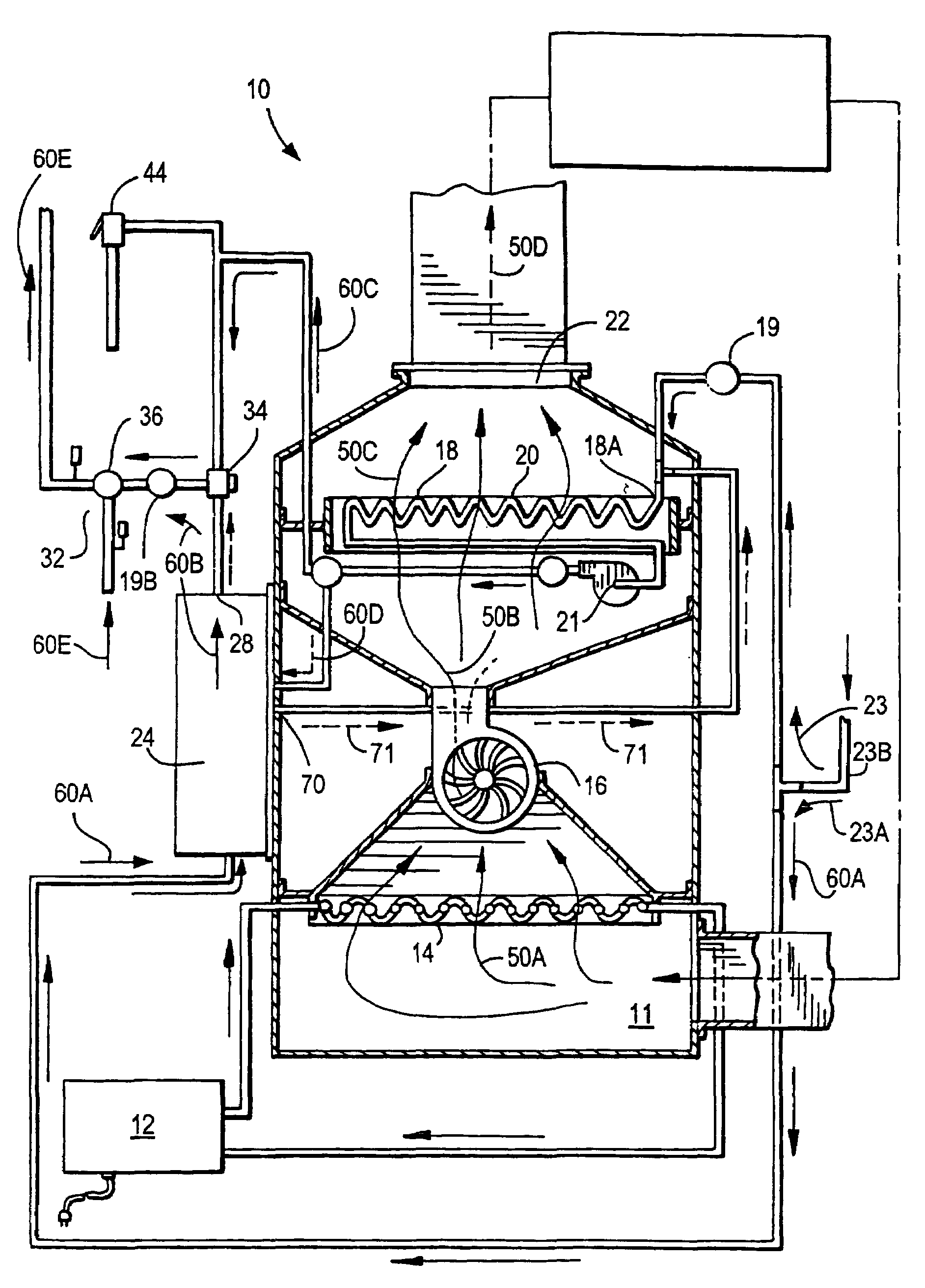
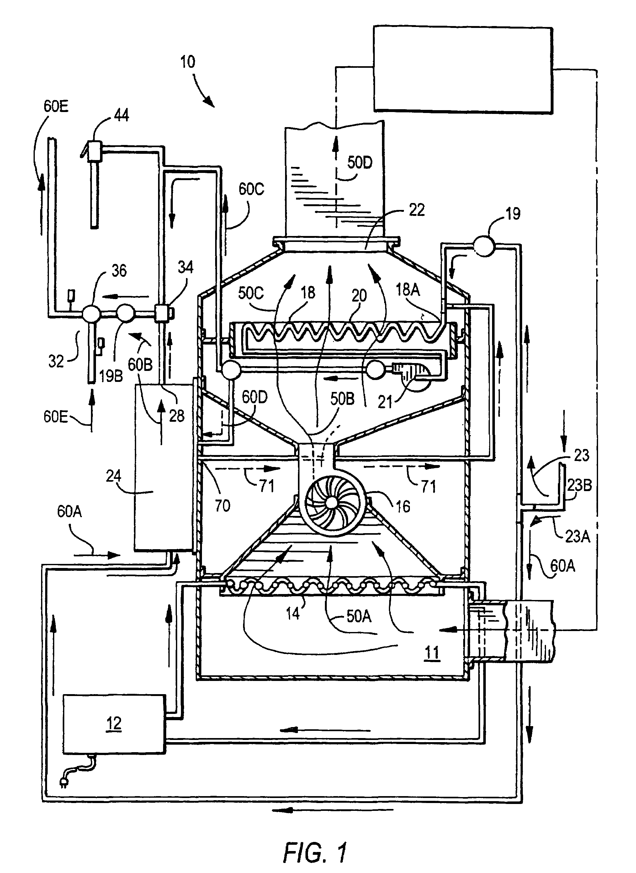
[0057]For convenience and clarity in describing these embodiments, similar elements or components appearing in different figures will have the same reference numbers.

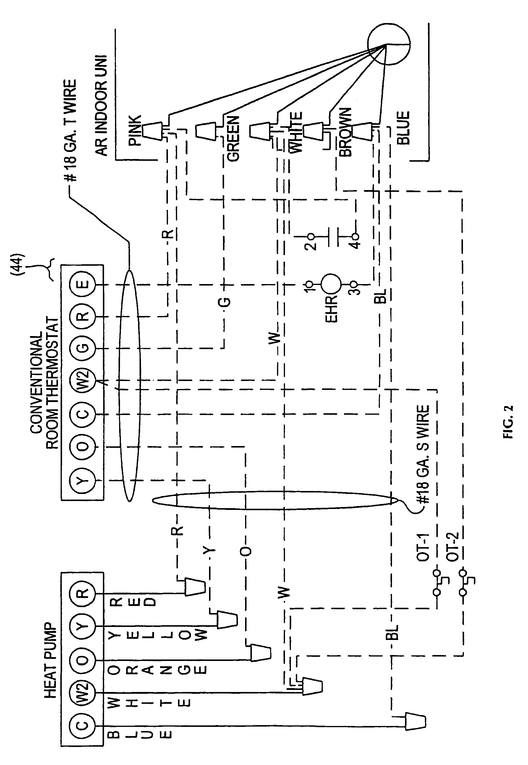
[0058]FIGS. 1-10 illustrate a preferred embodiment of the new electric forced hot air hydronic furnace. FIG. 1 provides an overall schematic view of the new furnace. For clarity and convenience reference numbers utilized in FIG. 1 are listed below along with the component or function that relates to each reference number:[0059]Furnace 10[0060]Return air inlet 11[0061]Heat pump 12[0062]Condenser coil 14[0063]Blower 16[0064]Hydronic coil heat exchanger 18[0065]Hydronic coil heat exchanger 18A[0066]Check valve 19A in cold water pipe to hydronic coil[0067]Check valve 19B in hot water flow to mixing valve 36[0068]Hydronic coil 20[0069]Water pump 21[0070]Forced air duct inlet 22[0071]Main cold water supply 23[0072]Cold water supply to flash heater 23A[0073]Cold water supply to hydronic coil 23B[0074]Flash heater 24[0075]Cold ...


PUM


Abstract

A furnace in combination with a heat pump and solar panels for providing domestic hot water and forced hot or cooled air utilizing heat pump achieved efficiency levels in an on-demand and unlimited domestic hot water, heating and air conditioning system. In heating mode, recycled air acquires heat from the heat pump's condenser coil and transfers this heat to the on-demand hot water.

Description

[0001]This invention claims the benefit of:[0002]a) U.S. Provisional Patent Application No. 60 / 645,944 filed Jan. 24, 2005,[0003]b) U.S. Provisional Patent Application No. 60 / 679,889 filed May 10, 2005 entitled Electric Forced Hot Air Hydronic Furnace, and[0004]c) U.S. Provisional Patent Application No. 60 / 680,075 filed May 11, 2005 entitled Solar Panel and Heat Pump Powered Electric Forced Hot Air Hydronic Furnace under 37 C.F.R.§§ 1.78 & 1.53 and other relevant sections.I. BACKGROUND[0005]A. Field of the Invention[0006]This invention is in the field of solar panel energy systems and furnaces and furnace systems for providing forced air heating and cooling and providing hot water, and particularly for providing forced air heating and cooling and on-demand domestic hot water in conventional single family homes and in other buildings and environments.[0007]B. Prior Art-Patent References[0008]Prior art patents of interest include U.S. Patent Numbers listed below, these patents being i...

Claims


Application Information

Patent Timeline
Patent Type & Authority Patents(United States)
IPC IPC(8): F24D9/00F24D3/08F24S10/95
CPCF24F3/001F24H4/02F24J2/04Y02B30/12Y02B10/20Y02E10/44F24S10/00
Inventor KAISER, STEWART R.
Owner AIR HYDRONIC PROD SOLUTIONS
Why Eureka
Try Eureka