Method of fabricating a complementary semiconductor device having a strained channel p-transistor

a technology of strained channel and semiconductor device, which is applied in the direction of semiconductor devices, basic electric elements, electrical appliances, etc., can solve the problems of limited operation speed of the semiconductor device as a whole, limited nanonization technology, and difficulty in achieving nanonization, etc., to achieve the effect of facilitating the formation of trenches, balancing the operation speed of the p-transistor and the operation speed of the n-transistor

Active Publication Date: 2008-08-05
FUJITSU SEMICON LTD
View PDF6 Cites 43 Cited by
  • Summary
  • Abstract
  • Description
  • Claims
  • Application Information

AI Technical Summary

Benefits of technology

[0010]An object of the present invention is to provide an innovational method for fabricating a semiconductor device having the operation speed of the p-transistor improved and balanced with the operation speed of the n-transistor.
[0012]According to another aspect of the present invention, the impurity implantation for forming the fist junction regions and the second junction regions is performed after the compressive stress applying portions have been formed, whereby the impurities, especially the impurity in the first junction regions is prevented from being diffused immediately below the gate insulation film by the thermal processing for forming the compressive stress applying portions. Accordingly, the short channel effect can be prevented, and the hole mobility of the channel region of the p-transistor is increased, whereby the operation speed of the p-transistor is balanced with that of the n-transistor to thereby increase the operation speed of the complementary semiconductor device as a whole. The drain current of the p-transistor can be increased, and also in the drain current, the characteristics of the p-transistor can be balanced with those of the n-transistor.
[0014]According to another aspect of the present invention, in addition to the above-described effects of the present invention, oxide film is formed on the surface of the semiconductor substrate in the second region by the first surface processing and the second surface processing, while an ashing deformed film which is inferior to the oxide film in hydrofluoric acid resistance is formed on the surface of the first region. That is, films which are different in the etching selectivity to hydrofluoric acid aqueous solution are formed on the surface of the semiconductor substrate in the first region and the second region. Accordingly, the surface of the semiconductor substrate only in the first region can be exposed by the hydrofluoric acid processing with the surface of the semiconductor device in the second region masked with the oxide film, which facilitates forming the trenches where the compressive stress applying portions are to be formed.

Problems solved by technology

In the generation of the minimum processing dimensions of below 65 nm including 65 nm, the nanonization is technologically very difficult, and the higher achievements resorting to the nanonization alone are being limited.
Furthermore, even when the operation speed of the n-transistor by using a strained silicon substrate, the operation speed of the semiconductor device as a whole cannot be achieved, but the cost increase, etc. by the use of the strained silicon substrate are problems.
Especially, the transistor whose gate length is below 100 nm including 100 nm has the problem that the roll off characteristics of the threshold voltage is deteriorated.

Method used


Image

  • Method of fabricating a complementary semiconductor device having a strained channel p-transistor
  • Method of fabricating a complementary semiconductor device having a strained channel p-transistor
  • Method of fabricating a complementary semiconductor device having a strained channel p-transistor

Examples


first embodiment

A First Embodiment

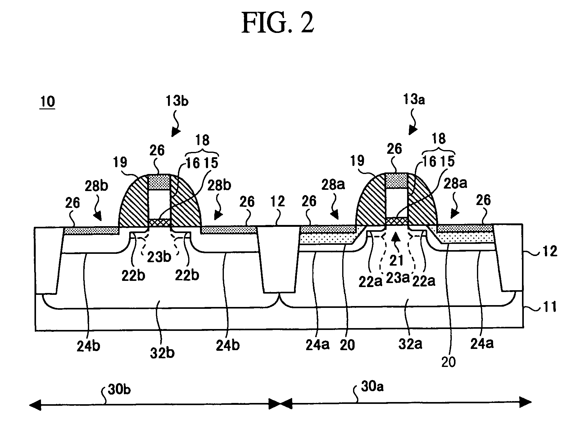
[0048]A semiconductor device fabricating method according to a first embodiment of the present invention will be explained with reference to FIGS. 2 to 17. FIG. 2 is a sectional view of a semiconductor device fabricated by the semiconductor device fabricating method according to the first embodiment of the present invention. FIGS. 3 to 17 are sectional view of the semiconductor device in the steps of the semiconductor fabricating method according to the present embodiment, which illustrate the method.

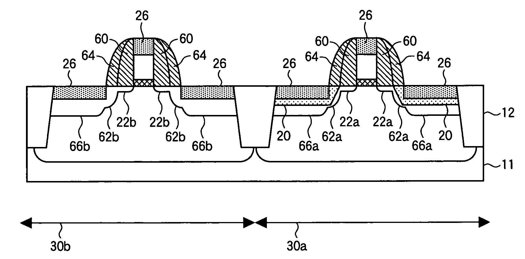
[0049]With reference to FIG. 2, the semiconductor device 10 comprises a p-MOS transistor 13a and an n-MOS transistor 13b spaced from each other by a device isolation region 12. In the p-MOS transistor 13a, compressive stress applying portions 20 of, e.g., SiGe are formed outward from the surfaces of the silicon substrate 11 in contact with a third sidewall insulation film 19 formed on both side surfaces of a gate layer structure 18 formed of a gate insulation film 15 a...

second embodiment

A Second Embodiment

[0092]The semiconductor device fabricating method according to a second embodiment of the present embodiment will be explained with reference to FIGS. 18 to 22. FIGS. 18 to 22 are sectional views of the semiconductor device in the steps of the semiconductor device fabricating method according to the second embodiment of the present invention, which illustrate the method. The parts of the semiconductor device corresponding to the parts explained above are indicated by the same reference numbers not to repeat their explanation.

[0093]The second embodiment of the present invention is characterized in that in etching the trenches for the compressive stress applying portions to be formed in, a mask which is different for that of the first embodiment is used.

[0094]First, in the step of FIG. 18, the same steps of FIGS. 3 to 6 of the first embodiment are performed to form the structure with a silicon oxide film 34-1 and a silicon nitride film 35-1 deposited, covering the s...

third embodiment

A Third Embodiment

[0109]The semiconductor device fabricating method according to a third embodiment of the present invention will be explained with reference to FIGS. 23 to 29. FIGS. 23 to 29 are sectional view of a semiconductor device in the steps of the semiconductor fabricating method according to the third embodiment, which illustrate the method. The same part as the parts described above are represented by the same reference numbers not to repeat their explanation.

[0110]The third embodiment of the present invention is different from the first embodiment I that the shallow junction regions are double-stepped.

[0111]The semiconductor device fabricating method according to the third embodiment is the same as the first embodiment in the steps of FIGS. 2 to 14. That is, in the step of FIG. 13, in an n-MOS region 30b, an n-impurity is implanted in a silicon substrate 11 on both sides of a gate layer structure 18 by ion implantation with the gate layer structure as the mask to form sh...


PUM


Abstract

Compression stress applying portions 20 of SiGe film are formed in the source / drain regions of the p-MOSA region 30a. Then, impurities are implanted in the p-MOS region 30a and the n-MOS region 30b to form shallow junction regions 22a, 22b and deep junction regions 23a, 23b. The impurity in the shallow junction regions 22a, 22b is prevented from being diffused immediately below the gate insulation film 15 by the thermal processing in forming the SiGe film, the short channel effect is prevented, and the hole mobility of the channel region of the p-MOS transistor 14a. The operation speed of the p-MOS transistor 13a is balanced with that of the n-MOS transistor, whereby the operation speed of the complementary semiconductor device 10 can be increased. The semiconductor device fabricating method can increase and balance the operation speed of a p-transistor with that of an n-transistor.

Description

CROSS-REFERENCE TO RELATED APPLICATIONS[0001]This application is based upon and claims priorities of Japanese Patent Application No. 2004-156569 filed on May 26, 2004 and Japanese Patent Application No. 2005-46573 filed on Feb. 23, 2005, the contents being incorporated herein by reference.BACKGROUND OF THE INVENTION[0002]The present invention relates to a semiconductor device fabricating method for fabricating a semiconductor device of complementary MIS (Metal Insulation Semiconductor) type having compression strain induced in the channel of the p-transistor.[0003]In semiconductor devices, for high achievements, as of speedy operation, low power consumption and high integration, etc., the minimum processing dimension has been increasingly nanonized. In the generation of the minimum processing dimensions of below 65 nm including 65 nm, the nanonization is technologically very difficult, and the higher achievements resorting to the nanonization alone are being limited.[0004]Here, as a...

Claims


Application Information

Patent Timeline
Patent Type & Authority Patents(United States)
IPC IPC(8): H01L21/336H01L21/76H01L21/8238
CPCH01L21/823807H01L21/823814H01L29/1083H01L29/7848H01L29/66628H01L29/66636H01L29/7842H01L29/6653H01L29/165H01L29/665H01L29/6656
Inventor KIM, YOUNG SUKMORI, TOSHIFUMI
Owner FUJITSU SEMICON LTD
Why Eureka
Try Eureka