Diagnostic instrument with movable electrode mounting member and methods for detecting analytes

Inactive Publication Date: 2008-10-14
FISH LEONARD
View PDF82 Cites 19 Cited by
  • Summary
  • Abstract
  • Description
  • Claims
  • Application Information

AI Technical Summary

Problems solved by technology

In clinical laboratories and large hospitals hundreds of samples are processed with expensive and large automated analyzers.
Although a glucose test by necessity is quantitative, strip tests are qualitative or semi-quantitative at best with very li

Method used


Image

  • Diagnostic instrument with movable electrode mounting member and methods for detecting analytes
  • Diagnostic instrument with movable electrode mounting member and methods for detecting analytes
  • Diagnostic instrument with movable electrode mounting member and methods for detecting analytes

Examples


first embodiment

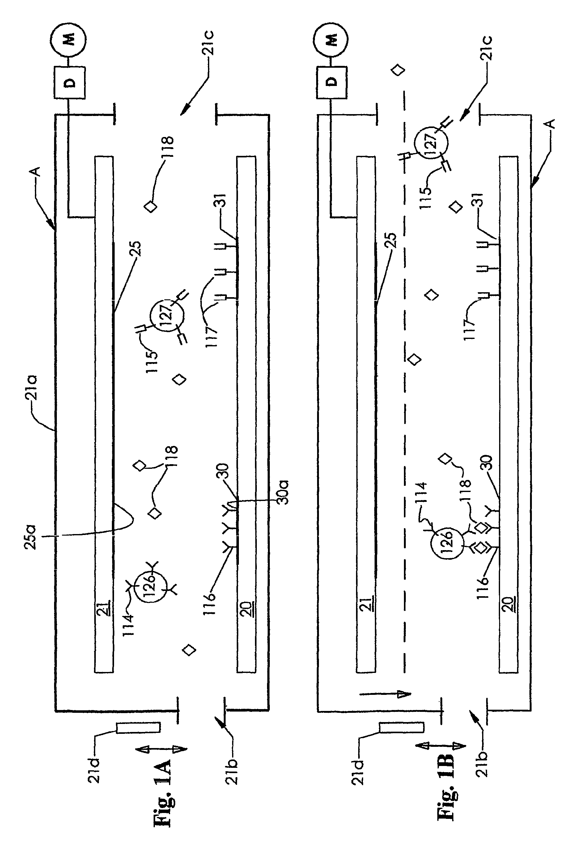
[0084]FIG. 1 depicts an instrument A including a pair of conductive electrodes 25 and 30, respectively mounted on insulator base support members 21 and 20. The electrodes 25 and 30 have substantially flat, planar surfaces 25a and 30a facing each other and each lying in different parallel planes. These electrodes 25 and 30 are directly opposed to each other vertically, and each have an area that exceeds about 0.5 square micrometer, and typically, each have an area of from about 10 square micrometers to about 10 square millimeters. The electrodes 25 and 30 are shown in a spaced apart position in FIG. 1A and, after introducing a sample and then removing unbound material from between the electrodes 25 and 30, moved to the dotted line position shown in FIG. 1B. As shown in FIG. 1B schematically, the electrodes 25 and 30 are brought into close proximity, almost but no t quite touching. Typically, the distance between the electrodes 25 and 30, when in the position shown in FIG. 1A, is from...

second embodiment

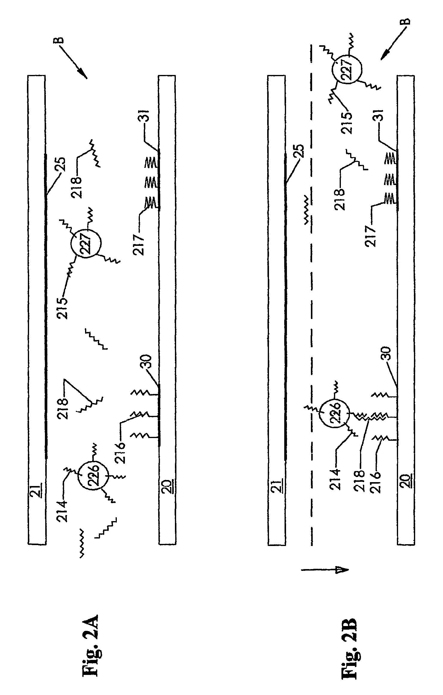
[0089]The second embodiment of this invention, the instrument B shown in FIG. 2, is similar to that shown in FIG. 1, but the housing 21a and motor M and drive mechanism D are not shown. This embodiment is a schematic representation of a DNA test. The electrodes 30 and 31 are coated with different probes, that is binding agents, respectively probes 216 and 217. The analyte or target 218 is able to bind with the probe 216 as well as with a probe 214 on the surface of the electrically readable particle 226. The probes 215 and 217 do not bind with the target 218. As discussed above in connection with FIGS. 1A and 1B, after binding of the target 218, unbound material is removed from the space between the electrodes 25 and 30 and the electrodes are moved towards each other and a detection circuit is then activated.

[0090]FIGS. 2C through 2G schematic represent another DNA test. In accordance with one aspect of this invention, as shown in FIGS. 2C through 2G, the conductive particles may be...

third embodiment

[0092]In FIGS. 3A and 3B, a competitive or inhibitory assay is illustrated using a third embodiment of this invention, the instrument C. The instrument C is similar to that shown in FIG. 1, but the housing 21a and motor M and drive mechanism D are not shown. In this third embodiment, analogs of analytes 316 and 317 are attached respectively to the surfaces of the electrodes 30 and 31, respectively. In the presence of the analyte 118 in the sample, binding to the electrically readable particle 126 is diminished. Failure of the particle 126 to bind to the first assay site due to the presence of the analyte 118 is a n indication that the analyte 118 is in the sample and the lack of binding will be detected by a detection circuit. In contrast, the particle 127 is bound to the analog 317 on the electrode 31 at the second assay site.

[0093]FIGS. 3C and 3D depict the particle 126 with the analog of the analyte 316 on the surface of the particle and the binding agents 116 on the electrode 30...


PUM


Abstract

An instrument (A) detects in a sample the presence of an analyte. The sample includes electrically readable particles (126) with an agent attached thereto that binds with the analyte or is an analog of the analyte. The instrument includes a port for the sample and a pair of electrodes (25, 30), one of which has a surface portion (30a) with an agent thereat that binds with the analyte or is an analog of the analyte. The electrodes have a first position where they are separated a sufficient distance apart to enable the sample to move between the electrodes and a second position where the electrodes are in close proximity. A detection circuit, including the electrodes, has a first state when the analyte is absent and a second state when the analyte is present. A signaling device provides an indication of the state of the detection circuit.

Description

RELATED PATENT APPLICATIONS[0001]This application is utility patent application based on a PCT application international application number PCT / US02 / 00461, international filing date Jan. 8, 2002, which in turn is based on U.S. provisional patent application Ser. No. 60 / 260,250, entitled “Diagnostic Instruments And Methods For Detecting Analytes,” filed Jan. 8, 2001. These related applications are incorporated herein by reference and made a part of this application.DEFINITIONSAs used herein:[0002]“analyte” means any molecule that is in a sample and is being assayed (analyzed);[0003]“analog of an analyte” means a chemically modified analyte, such as, for example, an analyte molecule connected to a linker molecule and will not bind with the analyte;[0004]“binding agent” means any molecule or group of molecules that that are able to interact with an analyte;[0005]“class of analyte” means a group of analytes that are detected b y closely similar methods: There are five main classes of cl...

Claims


Application Information

Patent Timeline
IPC IPC(8): G01N27/00G01N33/50G01N33/487G01N33/543
CPCG01N33/5438G01N33/54313B82Y15/00B82Y30/00Y10T436/143333
Inventor FISH, LEONARD
Owner FISH LEONARD
Why Eureka
Try Eureka