See-thru self cleaning biological filter system for aqua-culture

a filter system and aqua-culture technology, applied in the field of ornamental landscaping and aquaculture, to achieve the effect of rapid removal and unrestricted water flow

Inactive Publication Date: 2008-12-23
HOANG HUNG
View PDF17 Cites 19 Cited by
  • Summary
  • Abstract
  • Description
  • Claims
  • Application Information

AI Technical Summary

Benefits of technology

[0003]The present invention relates to the field of ornamental landscaping and aqua-culture and, in particular, to a filter system to efficiently, mechanically filter and remove solid wastes, biologically converting harmful chemicals and toxins to a safe and fish-healthy environment.
[0038]In a further aspect of the invention the improvement provides a strainer having a conical bottom portion with evenly spaced radial slots, a slot width and number of slots being adjusted to capture debris in filtering mode, prevent escape of biological filter media during backwash mode, and provide unrestricted water flow. The improvement also provides a filter tank being constructed with transparent material so as to permit visual inspection of the biological filter media, and a quick drain assembly having a vertical pipe with openings large enough to provide water flow for rapid removal of debris within the tank yet small enough to exclude the biological filter media.

Problems solved by technology

Water quality is the utmost important issue to all pond keepers.
Without an adequate filtration system two things happen: One, the water will not stay clear.
Decomposing or decaying debris, plants, or any organic matter will cloud the water, release toxic gases into the water, and consume oxygen.
This promotes algae growth which in turn consumes even more oxygen from the water.
Two, fish waste also produces toxins, and consumes oxygen and organic matter, thereby drastically reducing water quality.
Without an adequate filtration system the fish will literally die in their own waste.
However, cleaning a simple up-flow filter is untidy and inconvenient.
However, there are three major drawbacks in using sand as a filter.
First, the sediments collected at the top layer of the sand often cake up and the water will find its way to the bottom of the filter by channeling through the sand.
This renders the biological filtration ineffective.
Second, sand requires frequent backwashing (as often as 2 to 3 times per day with heavy fish loads), which can be a great inconvenience.
A suitable pump consumes considerable electrical energy.
However, there are still a few design limitations to the current state-of-the art systems available.
This mode of cleaning of the filter requires time and considerable water.
1) Over time, dirt, debris and other organic materials cause the floating beads to stick together and normal back-washing does not effectively remove all of the debris strained by the beads. Thus, especially in large tanks, a high flow volume air blower must be used to “unpack” the beads. This can create problems if the air blower is left on too long, (more than the seven minutes recommended by the manufacturer).
2) The air rising from the bottom to the top of the filter creates turbulence that scrubs away some of the beneficial bacteria on the surface of the beads. This causes a spike in ammonia and nitrite levels in the pond water that is considered stressful and may be dangerous to fish health. This elevated level of ammonia and nitrite in pond water may last as long as 3 to 5 days before filtration reduces it to a tolerable level. While the tight packing of the beads provides cleaner water, it also requires frequent cleaning of the filter every 7 to 10 days. So, while the bead filter is efficient, it also purges useful bacteria, limiting the overall effectiveness of the bead filter's biological filtration.
3) Bead media have a smooth outer surface and over time bacterial growth begins to form layers. The first layer of bacteria can be encapsulated by newer growth and can become anaerobic. This can impact fish health by consuming oxygen, lowering the pH level, increasing stress, and emitting harmful toxins into the water as underlying layers of bacteria decay.
4) Bead media are uniform in size. Thus they tend to pack uniformly, resulting in water channeling through the bead bed that greatly reduces filtering effectiveness.
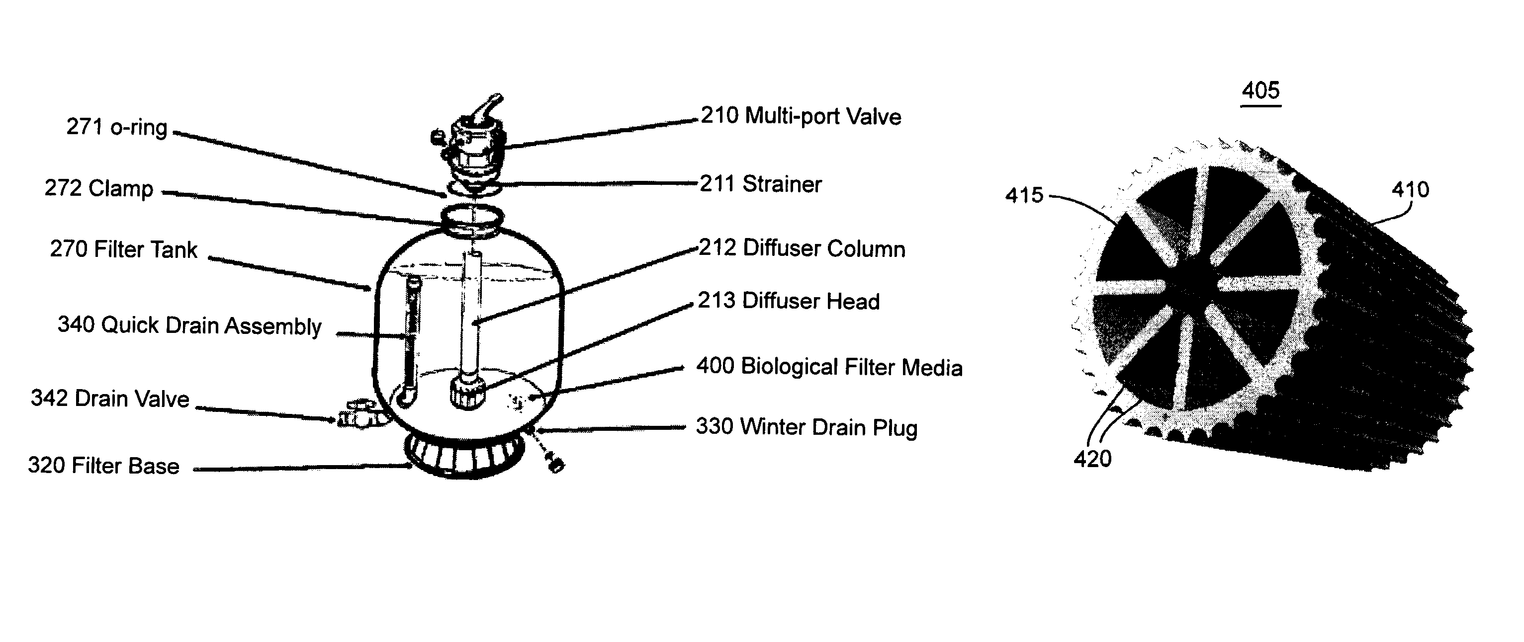
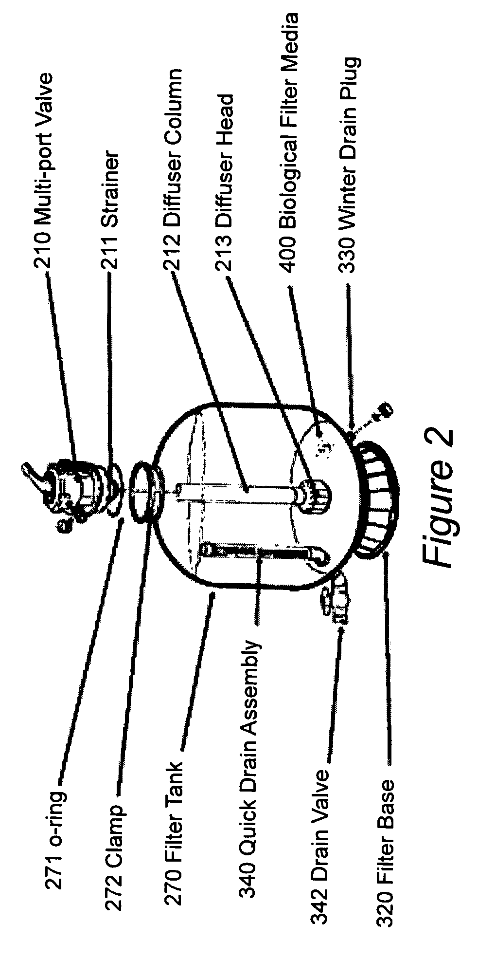
Second, water travels on the surface of the tubular media as well as through the hollow inner space of the media.
First, current systems continue to use components of a sand filter which have the diffuser column consisting of a number of lateral slot that have openings that are small, thus preventing the sand from passing through. This results in rapid clogging when the diffuser is used as a pond filter.
Second, the strainer does not have sufficient openings to allow the dirt to be removed from the filter bed quickly. Consequently, current systems consume a significant amount of water in backwashing the media bed. Furthermore, the openings in current systems are small circles, and this has the unfortunate effect of creating a water jet that stirs up the biological media at the top of the tank.
Third, a first diffuser head (with multiple lateral slots) is located at the bottom of the filter tank and a second diffuser head (generating spiral water jets) is located at the middle of the diffuser column. During backwash, the water is divided into two portions. One provides water to the laterals located at the bottom of the filter tank, lifting the media bed and dislodging dirt and debris from the media bed. At the same time, the combination of the second diffuser's water jets with the lateral jets at the bottom will stir the media bed in an upward spiral motion. This movement of the media bed further dislodges dirt and debris trapped within the media bed and directs the dirt and debris to the waste line through the multi-port valve. This diffuser column configuration has several disadvantages. Since the water is divided into two portions, the water that exits at the second diffuser head may not provide sufficient pressure in order to effectively stir and agitate the entire media bed. Also, the water that exits through the lateral slots at the bottom of the filter tank will not have enough water flow volume to rapidly dislodge dirt within the lower portion the media bed. Thus it will take more water to clean the entire media bed, resulting in energy inefficiency.
Fourth, the bio media is made of ABS plastic, a sinking type of bio media which requires more energy to clean, and is not made to be used for retrofitting of any bead systems on the market.

Method used


Image

  • See-thru self cleaning biological filter system for aqua-culture
  • See-thru self cleaning biological filter system for aqua-culture
  • See-thru self cleaning biological filter system for aqua-culture

Examples


Embodiment Construction

[0064]Referring now to the drawings, and more particularly to FIG. 1, there is shown an overview of a pond water filtration system. Water comes into the system from the pond through a water inlet 100, pulled by a pump 110 having a leaf basket for removing leaves. A check valve 120 prevents backflow from the filtration system. Water inlet 220 channels the pond water into the filter tank 270 via a multi-port control valve 210 controlled by valve control handle 200. The filter tank is mounted on a filter base 320. Filtered water is returned to the pond through water outlet 230. Waste is discharged through water outlet 350.

[0065]The purpose of this invention is to provide pond owners with an improved new water filtering system that is simple and easy to use, gives a maximum mechanical and biological filtration with significantly improved biological filter material, uses a see thru filter tank for monitoring the need for cleaning of the biological filtration material, has a new design of...


PUM

PropertyMeasurementUnit
lengthaaaaaaaaaa
lengthaaaaaaaaaa
lengthaaaaaaaaaa

Abstract

A system is described for collecting, filtering and removing dirt, debris, detritus, active organic materials, chemicals and toxins from water in fish ponds and general aqua-culture applications. This system includes a filter tank with supporting base containing biological filtration media, a multi-port valve, a strainer, a diffuser head, and a quick drain assembly. The filter tank is fabricated using transparent material allowing for visual inspection of the mechanical and biological activities inside the filter tank. The strainer and diffuser head are slotted so as to capture debris, retain filter media, and maintain unrestricted water flow. The quick drain is a vertical tube covered by drainage slots. The top end of the tube is capped. The bottom end of the tube extends through the filter tank wall to the exterior where a drain valve is attached. The biological filtration media are hollow plastic cylindrical structures with ridges on the external walls and free-standing fins on the internal walls that provide a high surface area-to-volume ratio and thus can support a high volumetric density of naturally occurring heterotrophic bacteria.

Description

DESCRIPTION[0001]This application claims the benefit of Provisional Application No. 60 / 642,098 of the same title filed on Jan. 10, 2005.BACKGROUND OF THE INVENTION[0002]1. Field of the Invention[0003]The present invention relates to the field of ornamental landscaping and aqua-culture and, in particular, to a filter system to efficiently, mechanically filter and remove solid wastes, biologically converting harmful chemicals and toxins to a safe and fish-healthy environment.[0004]2. Background Description[0005]For many years fish pond owners have tried to find an easy way to clean and maintain their ponds. Water quality is the utmost important issue to all pond keepers. Without an adequate filtration system two things happen: One, the water will not stay clear. Decomposing or decaying debris, plants, or any organic matter will cloud the water, release toxic gases into the water, and consume oxygen. This promotes algae growth which in turn consumes even more oxygen from the water. Two...

Claims


Application Information

Patent Timeline
Patent Type & Authority Patents(United States)
IPC IPC(8): C02F3/00C02F3/06B01D24/00B01D33/50
CPCA01K63/045C02F2103/007
Inventor HOANG, HUNG
Owner HOANG HUNG
Why Eureka
Try Eureka