
Plasma display panel with an improved electrode

a technology of plasma and electrodes, applied in the manufacture of electrode systems, cold cathode manufacturing, electric discharge tubes/lamps, etc., can solve the problems of deterioration of image quality of pdps, yellowing of glass substrates and dielectric layers, color temperature, etc., to achieve easy inhibition of panel yellowing, high luminance, and high quality

Inactive Publication Date: 2008-12-30
PANASONIC CORP
View PDF48 Cites 0 Cited by
  • Summary
  • Abstract
  • Description
  • Claims
  • Application Information

AI Technical Summary

Benefits of technology

[0012]It is an object of the present invention to provide a technique to relatively easily inhibit yellowing of the panel in a PDP in which silver electrodes are disposed on the substrates, and thus actualize a PDP that is capable of display images with high luminance and high quality.
[0017]On the contrary, in the present invention, the silver electrodes include an element or a compound whose standard electrode potential is lower than that of silver, or an element or a compound thereof, the element having higher ionization tendency than silver; therefore such an element or such a compound serves to inhibit ionization of the silver, and thus, it is possible to inhibit generation and diffusion of silver ions at times of baking. As a result, generation of silver colloidal particles around the silver electrodes is also inhibited, and thus yellowing of the panel can be prevented.
[0024]Further, it is possible to achieve the aforementioned object by having an arrangement wherein the silver-electrode-purpose paste used for forming the electrodes of the PDP includes a silver ionization inhibiting substance that is mentioned above.

Problems solved by technology

The PDPs comprising such silver electrodes as described above are known to have a problem that the glass substrates and the dielectric layer tend to turn yellow around the silver electrodes.
This yellowing in the glass substrates and the dielectric layer causes deterioration of luminance of blue cells, or a decrease in the color temperature at times of displaying full-white images, and may result in deterioration of image quality of the PDPs.

Method used


Image

  • Plasma display panel with an improved electrode
  • Plasma display panel with an improved electrode
  • Plasma display panel with an improved electrode

Examples


first embodiment

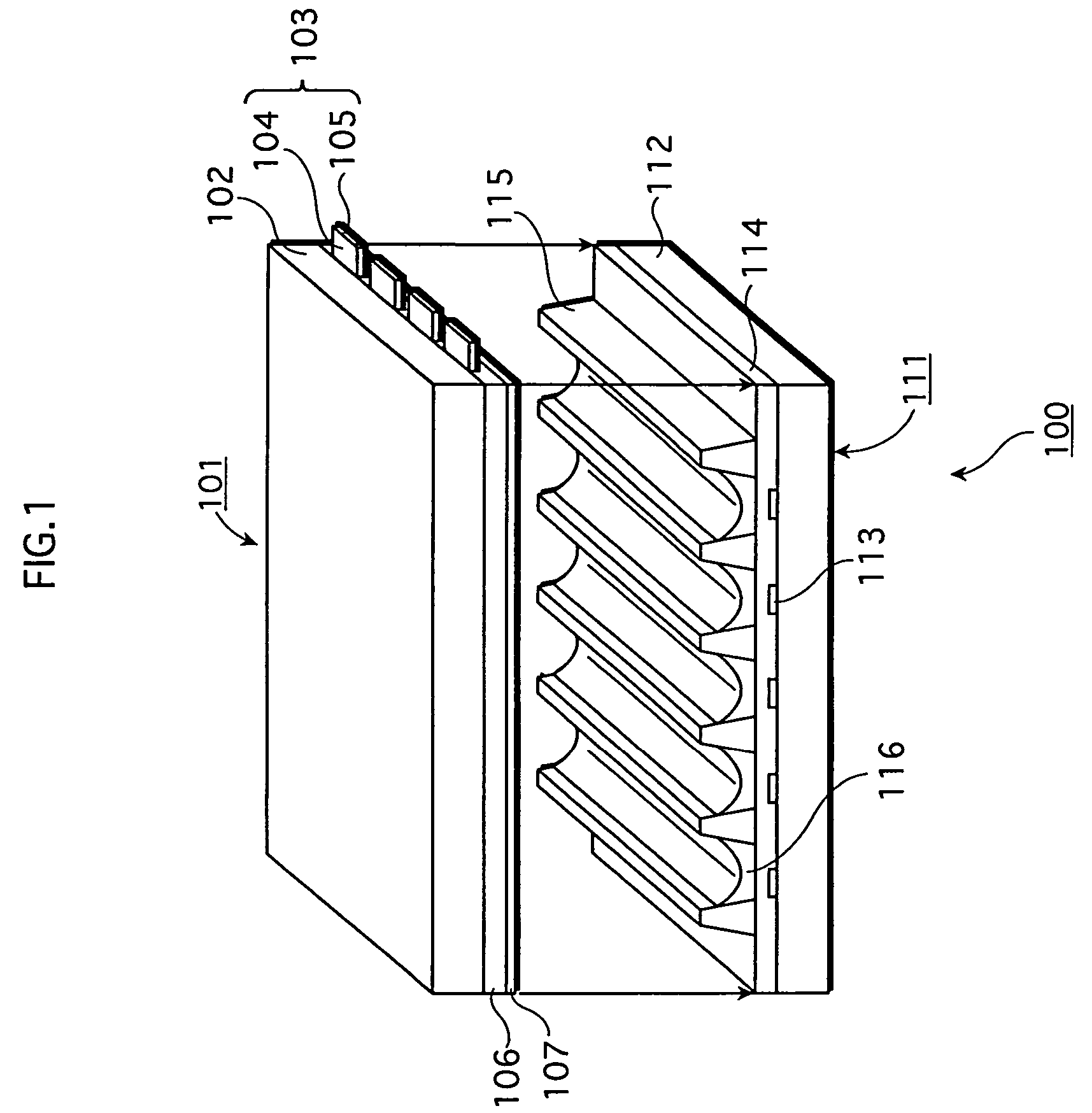
General Structure of the PDP

[0033]FIG. 1 is a perspective assembly drawing showing the structure of an AC surface-discharge type PDP 100 in the embodiments.

[0034]In the PDP 100, a front panel 101 as a first substrate and a rear panel 111 as a second substrate are pasted together with a perimeter sealing member (not shown in the drawing).

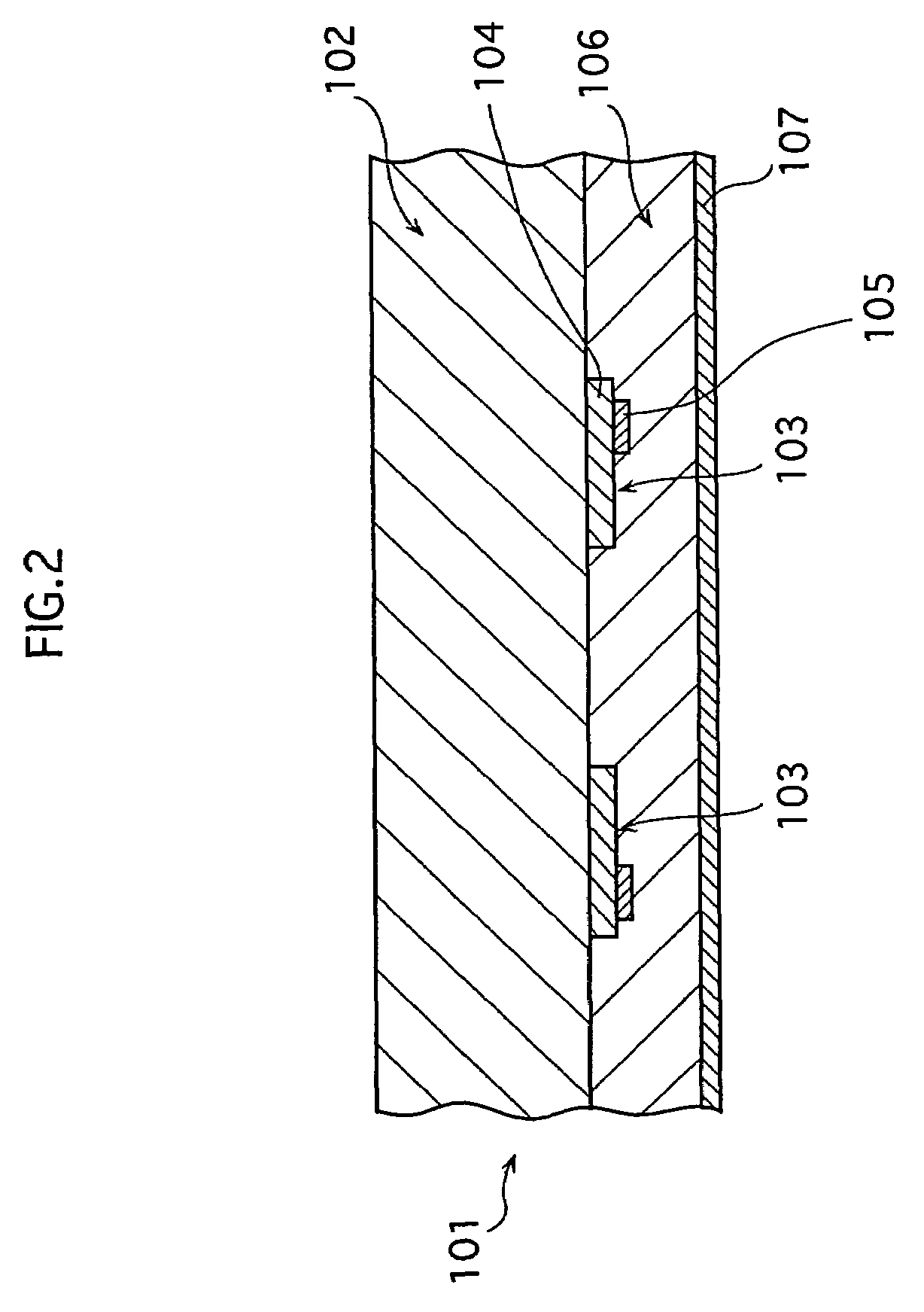
[0035]In the front panel 101, display electrodes 103 are disposed in stripes on a front glass substrate 102; and a dielectric glass layer 106 and a protective layer 107 made up of Magnesium Oxide (MgO) cover the display electrodes 103 from the top.

[0036]The rear panel 111 is made up of a rear glass substrate 112 on which address electrodes 113, a dielectric glass layer 114, barrier ribs 115, and phosphor layers 116 (in colors of red, green, and blue are arranged in order) are provided.

[0037]In the PDP 100, the space between the front glass substrate 102 and the rear glass substrate 112 is divided into sections by barrier ribs 115 and a discharge gas ...

second embodiments

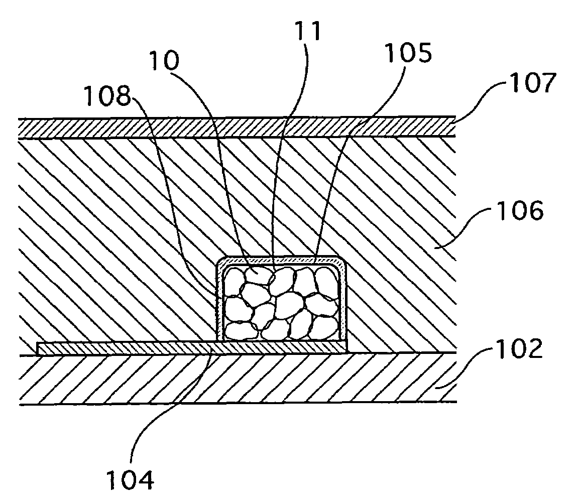
[0117]The PDP of the second embodiment has the similar structure to the PDP of the first embodiment, except that, in the second embodiment, a coating layer 108 made of a silver ionization inhibiting substance is formed on the surfaces of the silver electrodes 105, as shown in FIG. 6, whereas the silver ionization inhibiting substance exists in the silver electrodes 105 on the front panel 101 in the first embodiment.

[0118]As explained in the first embodiment, examples of a silver ionization inhibiting substance of which the coating layer 108 is made include: alkali metals (Li, Na, K, etc.); alkali-earth metals (Ca, Sr, Ba); Sc, Ti, V, Cr, Mn, Fe, Co, Ni, and Cu, which are transition metals (except for mercury and manganese) from which precious metals are excluded; an oxide, a hydroxide, a halide, a nitride, a carbide, a nitrate, a carbonate, and a sulfate of the elements above.

[0119]Preferred elements are Cr, Al, In, B, Ti, Ni, Pb, Zr, Sn, Zn, and Co. Preferred compounds are an oxide...

examples of embodiment

[0143]

TABLE 1Panel afterbaking theAdditive / dielectricSamplingCoveringAdditivememberPanel ColorNumberMaterialAmountValue a*Value b*Temperature1Cr5%−1.20.893002Al5%−1.81.590503In5%−1.51.989304B5%−2.52.089005Ti5%−2.21.390806Cover—−1.50.49500with Cr7Cover—−1.80.99350with AlCover8with—−1.30.89320Al2O39Cover—−1.51.29040with TiO210 Cover—−1.41.19120with SiO2*11 NoneNone−11.210.96400Sampling No. 11 is a comparison example

[0144]In Table 1, the PDPs shown with the sampling numbers No. 1 through No. 5 each comprise silver electrodes that include Cr, Al, In, B, or Ti respectively as a silver ionization inhibiting substance according to the first embodiment. Those silver electrodes are made using different silver pastes to which each silver ionization inhibiting substance is added by 5 wt % of the silver particles.

[0145]The PDPs shown with the sampling numbers No. 6 through No. 10 each comprise silver electrodes on the surfaces of which, according to the second embodiment, a coating layer made o...


PUM

PropertyMeasurementUnit
diameteraaaaaaaaaa
diameteraaaaaaaaaa
diametersaaaaaaaaaa

Abstract

An object of the present invention is to provide a technique for relatively easily suppressing the yellowing of a Plasma Display Panel in which electrodes comprising silver are disposed on the substrates, and thus render image displays with high luminance and high quality. In order to achieve the object, an arrangement is made in which the electrodes comprising silver further include an element whose standard electrode potential is lower than that of silver, such as Cr, Al, In, B, and Ti, or a compound of such an element, as a silver ionization inhibiting substance.

Description

DESCRIPTION[0001]1. Technical Field[0002]The present invention relates to plasma display panels used as display devices, particularly to plasma display panels comprising silver electrodes.[0003]2. Background Art[0004]In recent years, Flat Panel Displays (FPDs) have been attracting attentions as display devices used in bi-directional information terminal devices and the like.[0005]Different kinds of FPDs have been developed, such as Liquid Crystal Displays (LCDs), Plasma Display Panels (PDPs), Field Emission Displays (FEDs), Electro Luminescence Display (ELs), and some of these have already been put on the market.[0006]Among these FPDs, PDPs have characteristics that the other devices do not have, such as being self-luminous, being capable of displaying fine images, and being suitable for large-scale screens, and thus expectations are rising for the use of PDPs as wall-mounted large-screen TV displays.[0007]Generally speaking, in a PDP, light emitting cells of different colors are di...

Claims


Application Information

Patent Timeline
Patent Type & Authority Patents(United States)
IPC IPC(8): H01J11/02H01J9/02H01J17/04
CPCH01J9/02H01J11/12H01J11/24H01J2211/225H01J11/22
Inventor FUJITANI, MORIOYONEHARA, HIROYUKIAOKI, MASAKISUMIDA, KEISUKEASIDA, HIDEKIHIBINO, JUNICHIADACHI, DAISUKE
Owner PANASONIC CORP
Learn More