
Method for forming a thin film

Inactive Publication Date: 2009-01-27
SAMSUNG ELECTRONICS CO LTD
View PDF28 Cites 34 Cited by
  • Summary
  • Abstract
  • Description
  • Claims
  • Application Information

AI Technical Summary

Benefits of technology

[0015]The apparatus may further include a second pumping line, which bypasses the ozone decomposer, to protect the ozone decomposer from contamination caused by gas discharged during deposition of a dielectric film. The ozone decomposer connects to the ozonizer via an ozone purifying line, and a control valve on the pumping line directs the gas flow from the reaction chamber to the second pumping line or the ozone decomposer.
[0018]The steps (a) and (b) or the steps (a), (b), and (c) can be performed in situ in an apparatus. In particular, a reaction chamber including a shower head for source and annealing gases and a susceptor for heating the semiconductor substrate can perform steps (a) and (b). A first gas supply line that supplies a source gas for forming the dielectric film and a second gas supply line that supplies a reaction gas for forming the dielectric film and an annealing gas connect to the shower head. A second dielectric film may be further formed on the dielectric film and then annealed in situ in the same chamber. In the step (b), the semiconductor substrate can be annealed by a resistance heating or a lamp heating method. The source gas typically comprises a metal oxide gas corresponding to one selected from a group consisting of tantalum oxides such as pentaethoxytantalum (Ta(OC2H5)5), titanium oxides and aluminum oxides. When a tantalum oxide gas is the source gas, oxygen (O2) and ozone (O3) gases are the reaction gas and the annealing gas, respectively. In the step (a), the first gas supply line supplies the source gas, and the second gas supply line supplies the reaction gas. When there is a large difference in processing pressure between the steps (a) and (b), a turbo molecular pump (TMP) reduces the time required for adjusting the pressure between steps (a) and (b).
[0026]As described above, embodiments of the present invention share one gas supply for both forming and annealing of a thin dielectric film, and forming and annealing of the thin film are performed in situ in a chamber having the shared gas supply. Accordingly, the present invention can reduce the processing time of the thin film, thereby improving the productivity of a semiconductor device manufacturing process. In addition, inflow of impurities into the thin film is reduced, and equipment for forming and annealing of the thin film is simplified, reducing the amount of equipment required.

Problems solved by technology

One technique uses three-dimensional electrodes to increase the area (A) of the electrodes, but the three-dimensional electrodes are subject to structural restrictions.
In addition, a thinner dielectric film reduces the distance (d) between electrodes and produces higher capacitance of a capacitor, but reducing the distance (d) between the electrodes often has the drawback of increasing the leakage current of the capacitor.
However, with a tantalum pentoxide film, leakage current can be large when the film is thin.
A problem with tantalum pentoxide is non-uniform film deposition, and oxygen and carbon impurities often allow the leakage current through weak portions of the tantalum pentoxide film.

Method used


Image

  • Method for forming a thin film
  • Method for forming a thin film
  • Method for forming a thin film

Examples


Embodiment Construction

[0036]The present invention is described more fully with reference to the accompanying drawings, which illustrate embodiments of the invention. This invention may, however, be embodied in many different forms and should not be construed as being limited to the embodiments set forth herein; rather, these embodiments are provided so that this disclosure will be thorough and complete, and will convey the invention to those skilled in the art. It will also be understood that when a layer is referred to as being “on” another layer or substrate, the former can be directly on the latter, or intervening layers may also be present.

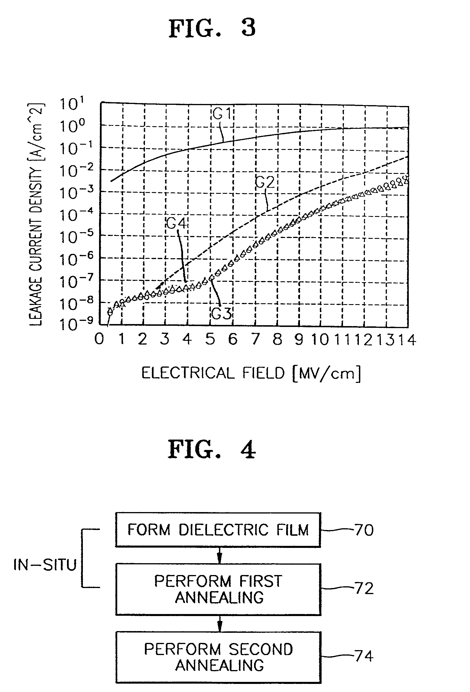
[0037]Prior to describing an apparatus for forming a dielectric film and a method for forming the dielectric film according to the present invention, the change in leakage current density of a dielectric film, e.g., a tantalum oxide (Ta2O5) film, according to the annealing method, is described.

[0038]Referring to FIG. 3, a tantalum oxide film was formed on a semicon...


PUM

PropertyMeasurementUnit
Temperatureaaaaaaaaaa

Abstract

A method for forming a film includes forming the film on a substrate, followed by performing a first annealing of the film at a temperature lower than a crystallization temperature of the film. A second annealing of the film is performed at a temperature higher that the crystallization temperature. Forming the film and the first annealing of the film are performed in situ in a chamber. Alternatively, the first and second annealing are performed in situ in an apparatus.

Description

CROSS REFERENCE TO RELATED APPLICATION[0001]This application is a division of and claims priority from U.S. patent application Ser. No. 09 / 350,407, filed Jul. 8, 1999 now U.S. Pat. No. 6,416,584, entitled, “Reaction Chamber and Method for Forming a Thin Film”, which claims priority from Korean Patent Application number 1998-27663 filed Jul. 9, 1998.BACKGROUND OF THE INVENTION[0002]1. Field of the Invention[0003]The present invention relates to manufacturing of a semiconductor device, and more particularly, forming of a thin film such as a dielectric film in a capacitor.[0004]2. Description of the Related Art[0005]The capacitance (C) of a capacitor is proportional to the area (A) of the capacitor's electrodes and a dielectric constant (∈) of a dielectric material between the electrodes, and inversely proportional to distance (d) between the electrodes, as shown in the following equation.C∝ε(A / d)[0006]Thus, increasing the area (A) of electrodes, using a dielectric film having a high d...

Claims


Application Information

Patent Timeline
IPC IPC(8): H01L21/285H01L27/10H01L21/31C23C16/40C23C16/56H01L21/316
CPCC23C16/405C23C16/56H01L21/31
Inventor WON, SEOK-JUNPARK, YOUNG-WOOKHYUNG, YONG-WOO
Owner SAMSUNG ELECTRONICS CO LTD
Features
  • Generate Ideas
  • Intellectual Property
  • Life Sciences
  • Materials
  • Tech Scout
  • Unparalleled Data Quality
  • Higher Quality Content
  • 60% Fewer Hallucinations
Learn More