
Beam homogenizer and laser irradiation apparatus

a laser irradiation and beam homogenizer technology, applied in the direction of optical elements, manufacturing tools, instruments, etc., can solve the problems of increasing the area occupied by the optical system, and achieve the effect of compact optical system, short distance between lenses, and short optical path length

Active Publication Date: 2009-02-03
SEMICON ENERGY LAB CO LTD
View PDF31 Cites 7 Cited by
  • Summary
  • Abstract
  • Description
  • Claims
  • Application Information

AI Technical Summary

Benefits of technology

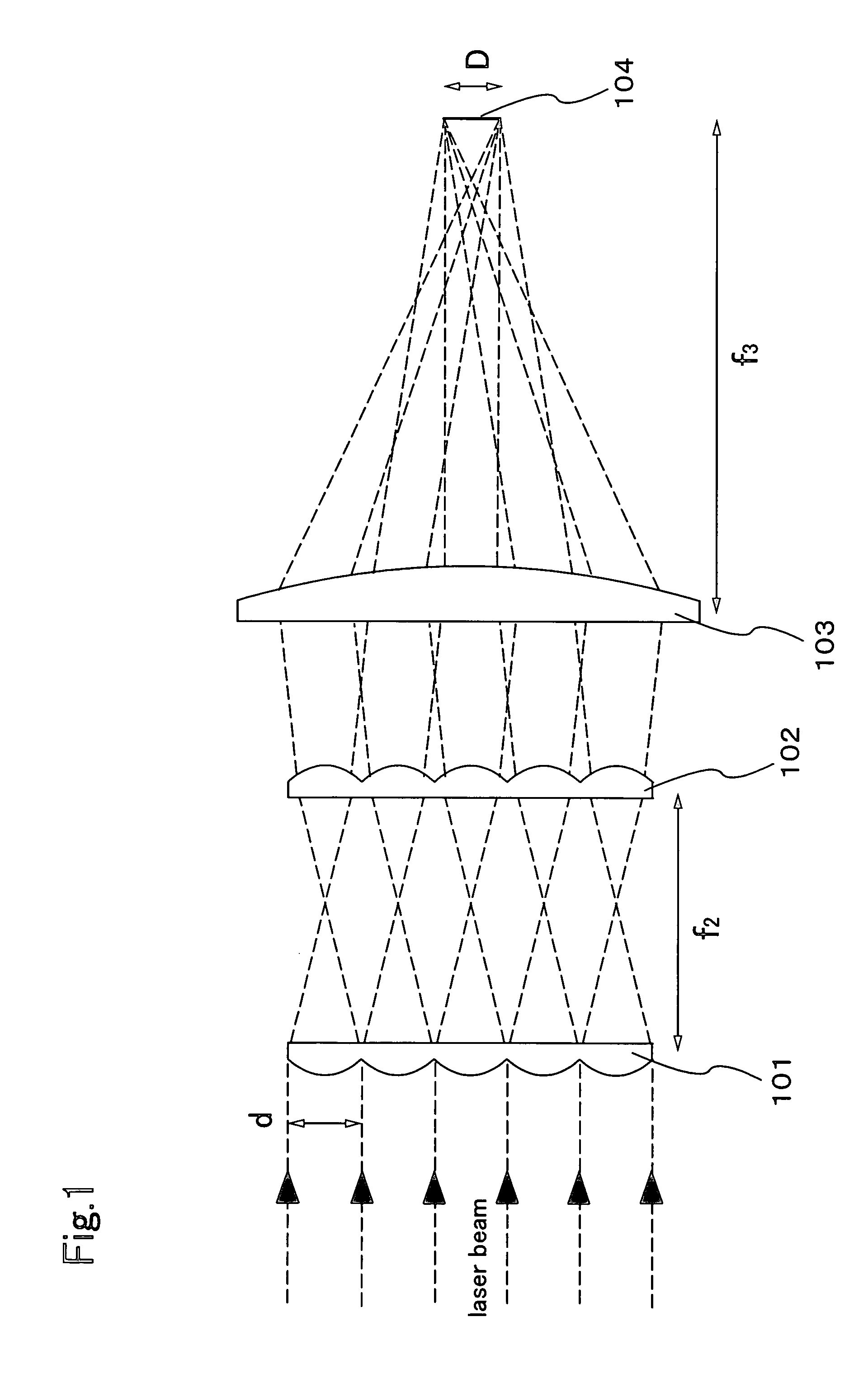
[0017]The present inventor has perfected the present invention as the result of concerted study directed towards eliminating this problem to provide a compact beam homogenizer for forming a rectangular beam, particularly a linear beam. Therefore, it is an object of the present invention to provide a beam homogenizer for homogenizing the energy distribution of a beam spot on an irradiation surface by using a more compact optical system, i.e., an optical system in which optical path length is shortened by decreasing the distance between lenses, and to provide a laser irradiation apparatus using the beam homogenizer.
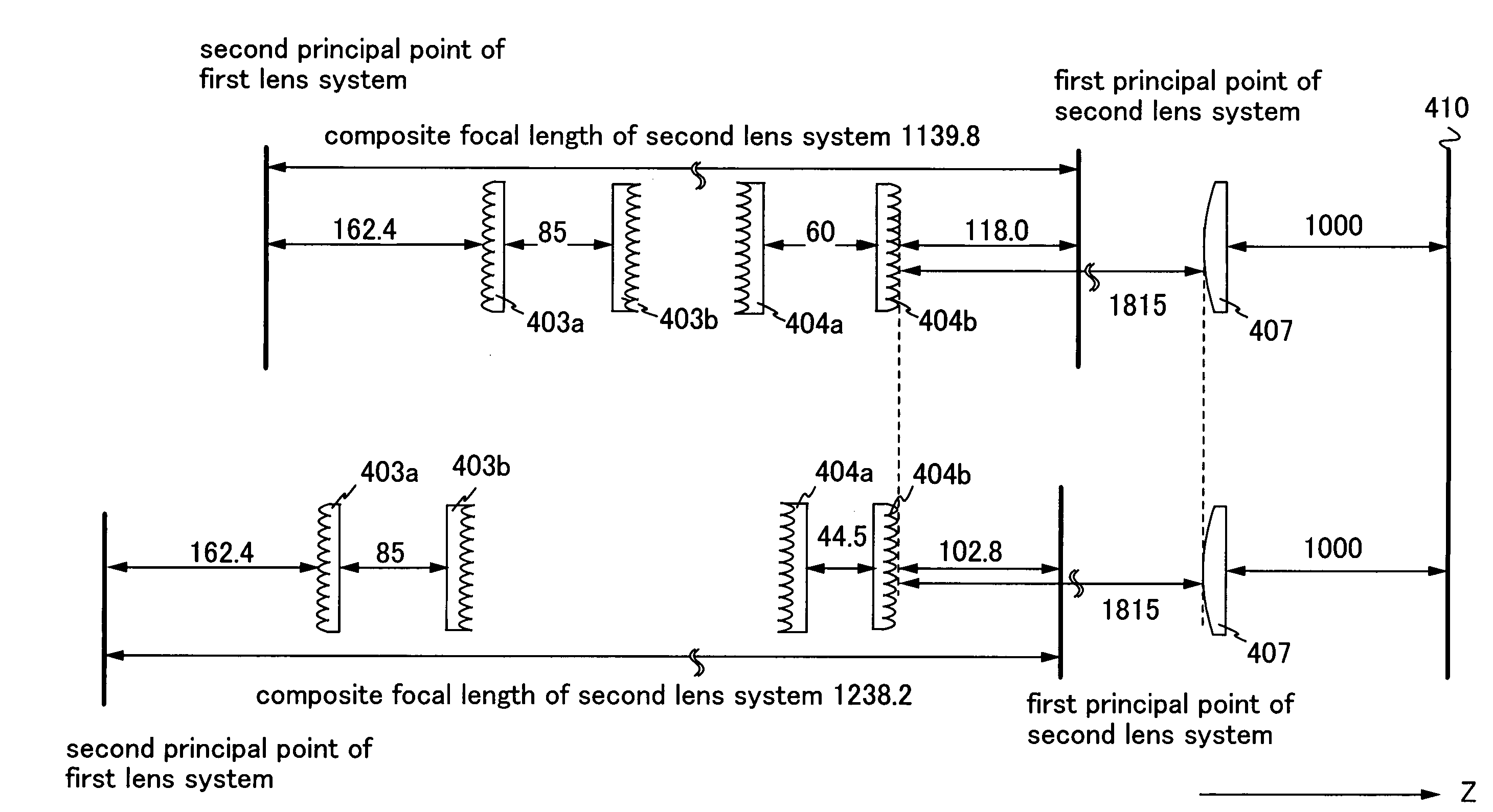
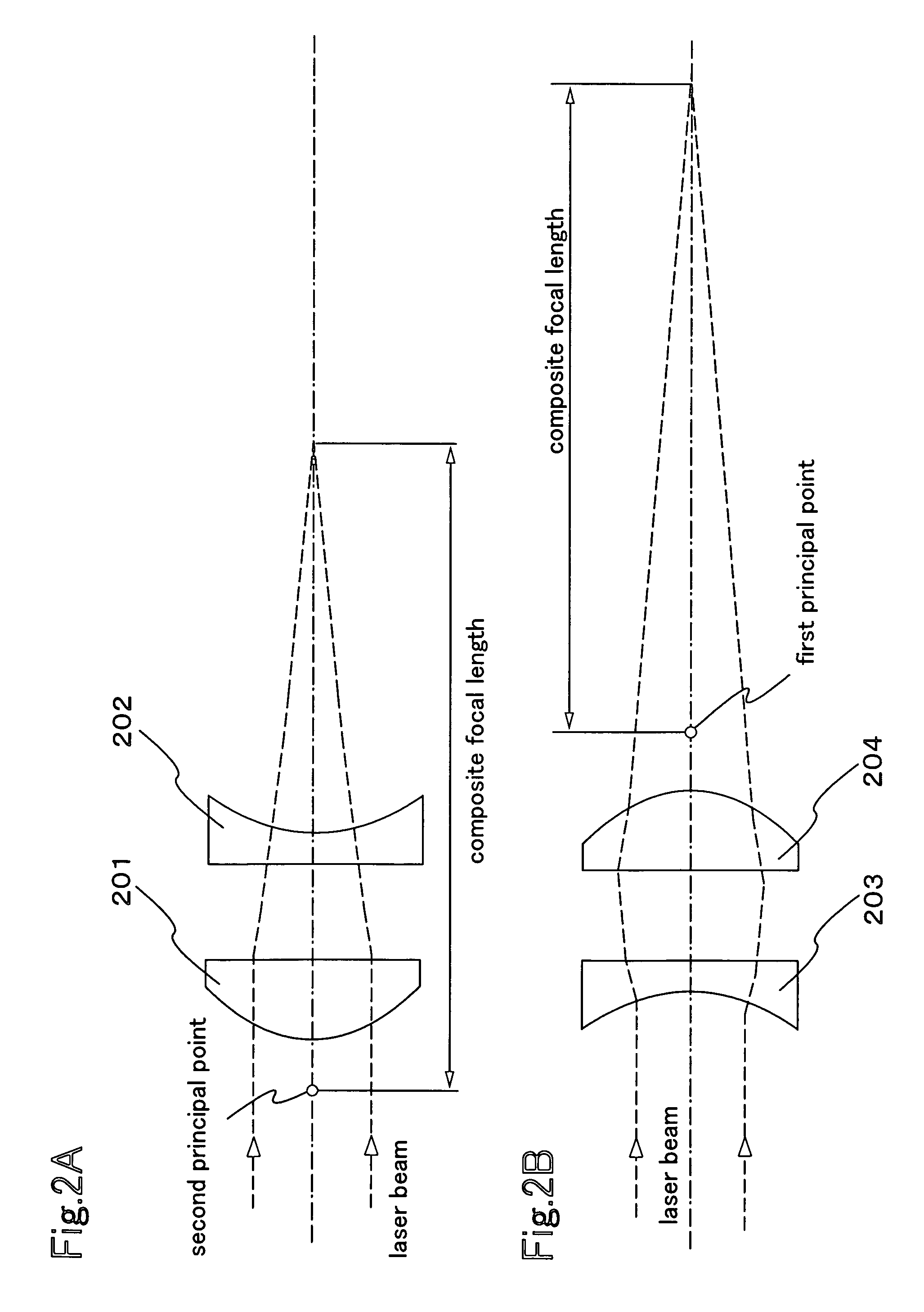
[0031]In the beam homogenizer of the present invention, by using the beam homogenizer equipped with each kind of array lens of an optical path shortened type including a lens system in which a convex lens and a concave lens are combined or the like, the position of a principal point of the lens system can be changed on purpose, whereby the distance between the lenses can be made short. Accordingly, the optical path length can be shortened. Therefore, it is possible to form a rectangular beam spot, particularly a linear beam spot, with homogeneous energy distribution on an irradiation surface by a more compact optical system. In the present invention, by using the beam homogenizer of the present invention in a laser irradiation apparatus, the space occupied by the optical system in the apparatus can be reduced, so that a more compact laser irradiation apparatus with smaller foot print can be provided.

Problems solved by technology

However, the extension of a linear beam in its long-side direction causes a problem in that the size of an optical system for forming the linear beam increases with the extension of the linear beam in its long-side direction, thereby increasing the area occupied by the optical system.

Method used


Image

  • Beam homogenizer and laser irradiation apparatus
  • Beam homogenizer and laser irradiation apparatus
  • Beam homogenizer and laser irradiation apparatus

Examples


embodiment 1

[0070]Embodiments of the present invention are hereinafter described with reference to the drawings. However, the present invention is not limited by the description of Embodiments but specified by the scope of claims. It is easily understood by those skilled in the art that the modes and details can be variously changed without departing from the spirit and scope of the present invention. In the structures of the present invention described hereinafter, the reference numeral indicating the same part is used in common in different drawings.

[0071]FIGS. 4A and 4B show an optical system employed in Embodiment 1. Embodiment 1 is described with reference to a side view of FIG. 4B. This side view includes in its paper a short-side direction of a linear beam spot formed by the optical system. A laser beam emitted from a XeCl excimer laser 401 travels in a direction indicated by arrows in FIGS. 4A and 4B. First, the laser beam is expanded by spherical lenses 402a and 402b. This structure is...

embodiment 2

[0087]This embodiment shows an example of a different optical system from the optical system described above, with reference to FIGS. 5A and 5B. In FIGS. 5A and 5B, a laser beam travels along the same optical path as that in the optical system shown in FIGS. 4A and 4B described in Embodiment 1 except the optical path in a cylindrical lens array that forms a homogenizer in a short-side direction. A beam homogenizer shown in this embodiment is described with reference to a side view of FIG 5B. It is to be noted that the lenses shown in this embodiment are made of synthetic quartz having high transmittance and laser resistance against a XeCl excimer laser.

[0088]The laser beam emitted from the laser oscillator is divided by a cylindrical lens array 503 hereinafter described in a short-side direction. The cylindrical lens array 503 has eleven cylindrical lenses arranged in a direction of the curvature, each of which has a first surface with a radius of curvature of 412.8 mm, a second sur...

embodiment 3

[0092]This embodiment will show an example of a different optical system from the optical system shown above, with reference to FIGS. 8A and 8B. Similarly to another embodiment, the lenses shown in this embodiment are made of synthetic quartz having high transmittance and laser resistance against a XeCl excimer laser; however, the material of the lens can be selected appropriately in accordance with a laser and a wavelength range to be used. FIG. 8A shows only an optical system for homogenizing the energy density distribution of the beam in the short-side direction. The optical system for homogenizing the energy density distribution in the long-side direction is used similarly to another embodiment.

[0093]The cylindrical lens arrays 403a and 403b used here correspond to the front side array lens of an optical path shortened type in the beam homogenizer of the present invention, and FIG. 8B shows an optical system in which a cylindrical lens array 801 with both of its first surface an...


PUM

PropertyMeasurementUnit
lengthaaaaaaaaaa
wavelengthaaaaaaaaaa
aspect ratioaaaaaaaaaa

Abstract

The present invention provides a beam homogenizer for homogenizing energy distribution by making the distance between lenses small to shorten the optical path length with the use of an array lens of an optical path shortened type, and a laser irradiation apparatus using the beam homogenizer. The beam homogenizer is equipped with a front side array lens of an optical path shortened type whose second principal point is positioned ahead on a beam incidence side, a back side array lens of an optical path shortened type whose first principal point is positioned behind on a beam emission side, and a condensing lens, wherein the distance between the second principal point of the front side array lens and the first principal point of the back side array lens is equal to the focal length of the back side array lens.

Description

BACKGROUND OF THE INVENTION[0001]1. Field of Invention[0002]The present invention relates to a beam homogenizer which homogenizes the energy distribution of a beam spot on an irradiation surface by using a more compact optical system, and also relates to a laser irradiation apparatus using the beam homogenizer. More specifically, the present invention relates to a beam homogenizer which homogenizes the energy distribution of a beam spot on an irradiation surface by using a more compact optical system obtained by decreasing the distance between lenses to shorten optical path length, and also relates to a laser irradiation apparatus using the beam homogenizer.[0003]2. Description of the Related Art[0004]In recent years, research has been widely conducted on techniques for carrying out laser annealing to a non-single crystal semiconductor film (an amorphous semiconductor film or a semiconductor film having crystallinity which is not single crystal, such as poly-crystal or microcrystal)...

Claims


Application Information

Patent Timeline
Patent Type & Authority Patents(United States)
IPC IPC(8): G02B27/10
CPCB23K26/0639B23K26/0648B23K26/0665B23K26/067G02B27/0961G02B27/0966B23K26/064
Inventor MORIWAKA, TOMOAKI
Owner SEMICON ENERGY LAB CO LTD
Learn More