
High mass throughput particle generation using multiple nozzle spraying

a multi-nozzle, particle technology, applied in the direction of packaging foodstuffs, pharmaceutical containers, packaged goods, etc., can solve the problems of inability to increase the mass throughput of such an electrospray device that can produce nanoparticles, the potential impact of nanoparticle technology on the pharmaceutical industry, and the inability to achieve the effect of high mass throughpu

Inactive Publication Date: 2009-03-03
RGT UNIV OF MINNESOTA
View PDF178 Cites 140 Cited by
  • Summary
  • Abstract
  • Description
  • Claims
  • Application Information

AI Technical Summary

Benefits of technology

[0011]For the above reasons, there is a need in the art for mass throughput apparatus and methods which overcome the problems described above, and other problems as will become apparent to one skilled in the art from the detailed description below. The present invention provides apparatus and methods that produce nanoparticles with high mass throughput, e.g., can produce large quantities of nanoparticles for use in various applications, e.g., pharmaceutical, biological material production for gene therapy, coatings, fabrication processes, etc.

Problems solved by technology

For example, new chemicals being synthesized as future drug products are decreasing in aqueous solubility to such an extent as to present major delivery and development challenges.
Thus, nanoparticle technology has the potential to significantly impact the pharmaceutical industry.
One limiting factor in employing electrospray or electrohydrodynamic techniques for particle generation is that generally only a single spray-nozzle dispenser is used that can deliver only a small quantity of solution, e.g., a few μl / min.
A major challenge and problem is the inability to increase the mass throughput from such an electrospray device that can produce nanoparticles so that electrohydrodynamic techniques can be used to deliver industrial quantities particles for use in various products.
However, problems associated with multiple nozzle approaches are not addressed, e.g., the space charge effect of particles produced using electrospray techniques, arcing between nozzles, etc.

Method used


Image

  • High mass throughput particle generation using multiple nozzle spraying
  • High mass throughput particle generation using multiple nozzle spraying
  • High mass throughput particle generation using multiple nozzle spraying

Examples


Embodiment Construction

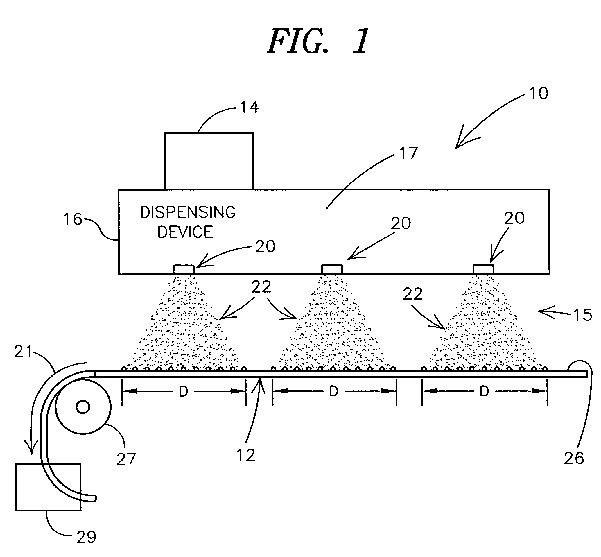
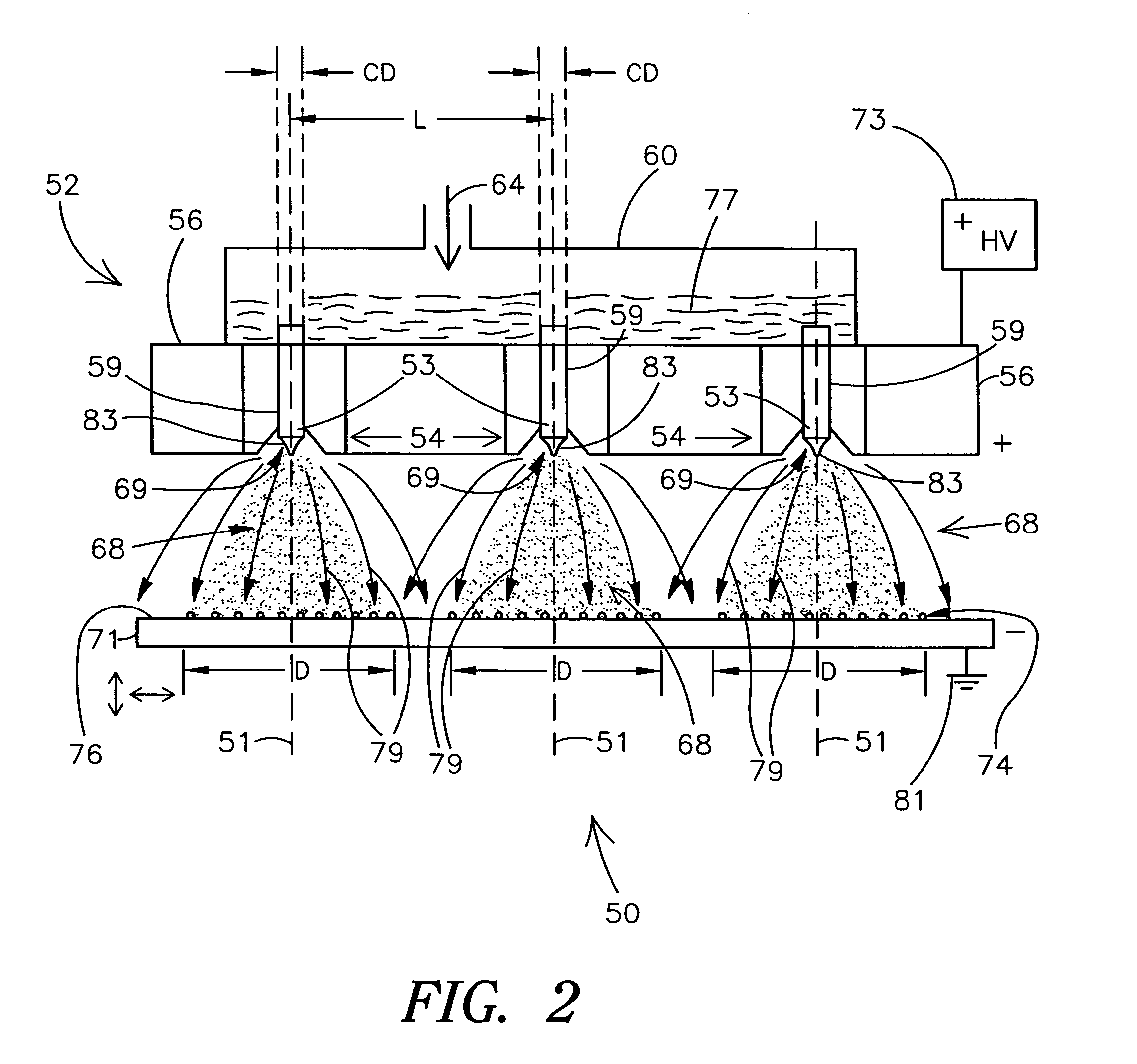
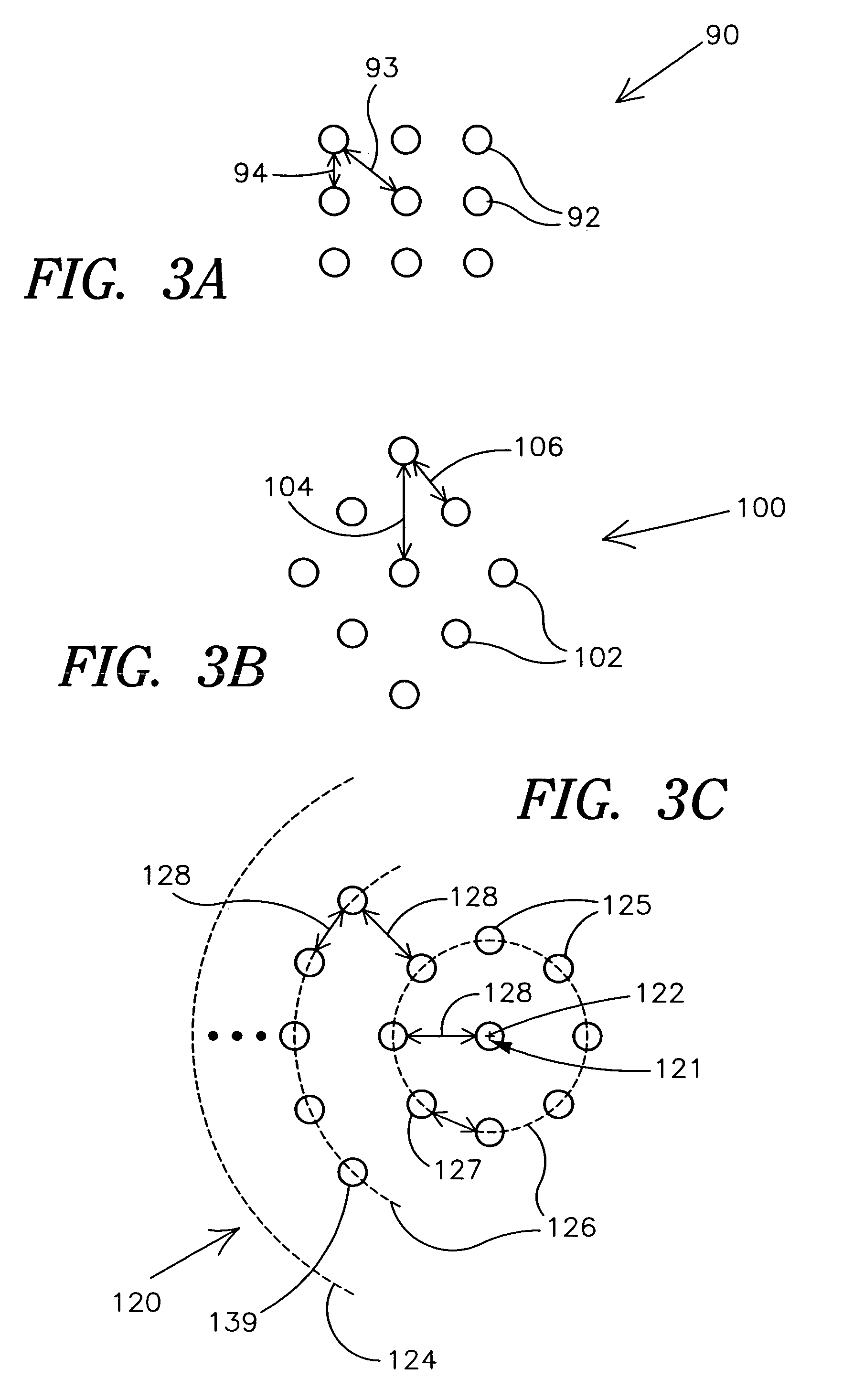
[0032]The present invention shall first generally be described with reference to FIG. 1. Various embodiments of the present invention shall then be described further with reference to FIGS. 2-17. It will become apparent to one skilled in the art that elements from one embodiment may be used in combination with elements of the other embodiments and that the present invention is not limited to the specific embodiments described herein, but only as described in the accompanying claims.

[0033]The present invention provides spraying apparatus and methods that employ multiple nozzle structures for producing multiple sprays of particles, e.g., uniform size nanoparticles. Conventional single nozzle spraying apparatus and methods have been used for producing nanoparticles, however, such apparatus and methods provide a very small throughput that is not suitable for practical production of a large quantity of nanoparticles for applications, e.g., high tech applications such as in the manufactur...


PUM

PropertyMeasurementUnit
diameteraaaaaaaaaa
diameteraaaaaaaaaa
diameteraaaaaaaaaa

Abstract

Spraying apparatus and methods that employ multiple nozzle structures for producing multiple sprays of particles, e.g., nanoparticles, for various applications, e.g., pharmaceuticals, are provided. For example, an electrospray dispensing device may include a plurality of nozzle structures, wherein each nozzle structure is separated from adjacent nozzle structures by an internozzle distance. Sprays of particles are established from the nozzle structures by creating a nonuniform electrical field between the nozzle structures and an electrode electrically isolated therefrom.

Description

CROSS-REFERENCE TO RELATED APPLICATIONS[0001]This application is a continuation application of Ser. No. 09 / 858,865, filed on May 16, 2001 (now U.S. Pat. No. 6,764,720), which claims the benefit under 35 U.S.C. §119(e) of U.S. Provisional Patent Application No. 60 / 204,451, filed on May 16, 2000, which are all incorporated herein by reference in their entirety.STATEMENT OF GOVERNMENT SUPPORT[0002]The invention was made with the support of U.S. Department of Energy grant number DE-FG02-98ER14909. The United States government may have certain rights to the invention.TECHNICAL FIELD[0003]The present invention relates generally to spray apparatus and methods. More particularly, the present invention pertains to multiple nozzle spray methods and apparatus, e.g., multiple nozzle electrospray methods and apparatus.BACKGROUND OF THE INVENTION[0004]It has been recognized that microsphere production technology can produce drugs or pharmaceuticals that can be taken up by cells, e.g., cells in an...

Claims


Application Information

Patent Timeline
Patent Type & Authority Patents(United States)
IPC IPC(8): B05D1/04A61J3/06A61F2/86A61L31/10A61L31/16B05B1/14B05B5/025B05B5/08B05B7/04B05B7/06B05B13/06
CPCB05B1/14B05B5/025B05B5/0255B05B5/08B05B5/087B05B7/0408B05B7/066B05B5/032A61F2/86B05B13/06
Inventor PUI, DAVID Y. H.CHEN, DA-REN
Owner RGT UNIV OF MINNESOTA
Learn More