Light emitting diode structures

a technology of light-emitting diodes and structures, which is applied in the direction of instruments, optical elements, optical waveguide light guides, etc., can solve the problems of reducing the efficiency of light extraction, so as to improve the extraction efficiency, and improve the effect of mode confinemen

Active Publication Date: 2009-03-24
QUANTUM NIL LTD +1
View PDF16 Cites 10 Cited by
  • Summary
  • Abstract
  • Description
  • Claims
  • Application Information

AI Technical Summary

Benefits of technology

[0021]Preferably, the Fourier transform of the array has a degree of rotational symmetry n, where n>6. The high degree of symmetry of photonic quasicrystals of this type results in photonic bandgaps with a high degree of isotropy. Complete bandgaps can be achieved even with a low refractive index contrast.
[0023]LEDs incorporating photonic quasicrystals in accordance with the present invention have an improved extraction efficiency over conventional LEDs and over LEDs incorporating regular photonic crystals. Quasicrystal structures offer a number of benefits. For example, more isotropic bandgaps found in Photonic quasicrystals leads to greater mode confinement and hence greater extraction efficiency. It is noted that ordinary photonic crystals suffer from anisotropic bandgaps which do not overlap for different propagation directions (except for high refractive index contrasts) and hence do not confine a single wavelength of light with the same penetration depth in all directions. Furthermore, the long range order which is a property of quasicrystals leads to more uniform far field diffraction patterns. Close packing of regions made possible in quasicrystal structures leads to a greater surface area through which photons can exit the structure and hence greater extraction efficiency.

Problems solved by technology

Notwithstanding those benefits, most of the light generated inside a conventional LED cannot be efficiently extracted from the active layer.
This in turn dramatically restricts the external quantum efficiency compared to that of the internal quantum efficiency.
While this method is efficient at extracting light that is experiencing multiple total internal reflections due to absorptive regions within an LED, the light is rapidly attenuated and hence does not contribute to orders of magnitude light extraction and improvement.
It is well known that it is generally not desirable to etch into the active layer due to increased surface recombination of carriers, which affects the overall photoluminescence quantum efficiency of the active layer.

Method used


Image

  • Light emitting diode structures
  • Light emitting diode structures
  • Light emitting diode structures

Examples


Embodiment Construction

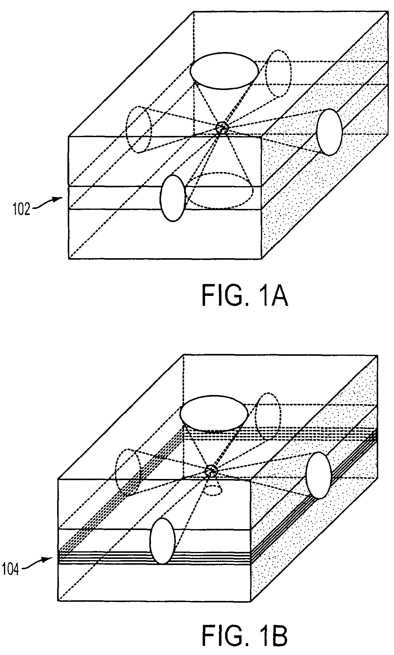
[0059]There are three possible uniform tilings of the plane by regular polygons, using squares, triangles or hexagons. In 1-uniform tilings there is only one type of vertex in the plane. Additionally there are 13 different orientations for filling the space using 1-uniform (Archimedian) tilings. These tiling patterns form the basis of what, in this specification, will be referred to as regular 2D photonic crystals. Regular 2D photonic crystals are typically formed in dielectric material and have an array of regions forming a periodic variation in refractive index, the periodicity based on one of the uniform tilings of the plane. The simplest example of a photonic crystal of this type is an array of holes in a dielectric slab, an etched air rod being positioned at each vertex of a uniform tiling pattern.

[0060]Photonic crystals offer unique ways to tailor light and the propagation of electromagnetic (EM) waves. By analogy to electrons in a crystal, EM waves propagating in a structure ...


PUM


Abstract

According to one aspect of the present invention, a light emitting diode (LED) structure including an active core layer and at least one substrate layer having a first refractive index, comprises a 2-dimensional photonic quasicrystal in the structure, the photonic quasicrystal comprising an array of regions having a second refractive index, the array exhibiting long range order but short range disorder. The long range order is associated with diffractive properties of the structure and gives rise to uniform-far field diffraction patterns from the LED. The present invention enjoys the benefit of improved light extraction from LEDs without undesirable far field illumination patterns.

Description

FIELD OF THE INVENTION[0001]The present invention relates to light emitting diodes (LEDs) and in particular to LEDs with improved efficiency.BACKGROUND TO THE INVENTION[0002]LEDs have many potential applications. For example, LEDs can be used in displays, such as LCDs and in projection, entertainment, general lighting and automotive applications where high brightness and compact illumination is required. The benefits of LEDs over conventional incandescent lighting and halogen lighting are high brightness, long life, instant operation, energy saving, environmental friendliness, durability and compactness.[0003]Notwithstanding those benefits, most of the light generated inside a conventional LED cannot be efficiently extracted from the active layer. Almost 80% of the light generated in an LED is outside the escape cone of the structure. Most of the light remains either guided in the core or totally internally reflected in the high refractive index substrate layer.[0004]The potential f...

Claims


Application Information

Patent Timeline
Patent Type & Authority Patents(United States)
IPC IPC(8): G02B6/10H01L33/20H01L33/24
CPCB82Y20/00H01L33/20H01L33/24H01L2933/0083
Inventor ZOOROB, MAJDLINCOLN, JOHN
Owner QUANTUM NIL LTD
Why Eureka
Try Eureka