Optical film and optical compensatory film, polarizing plate and liquid crystal display using same

a technology of optical compensatory film and liquid crystal display, applied in the direction of instruments, transportation and packaging, synthetic resin layered products, etc., can solve the problems of narrow viewing angle and inability to meet the demands of the above-mentioned art, and achieve the effect of suppressing color shift and high contras

Inactive Publication Date: 2009-06-02
FUJIFILM CORP +1
View PDF15 Cites 5 Cited by
  • Summary
  • Abstract
  • Description
  • Claims
  • Application Information

AI Technical Summary

Benefits of technology

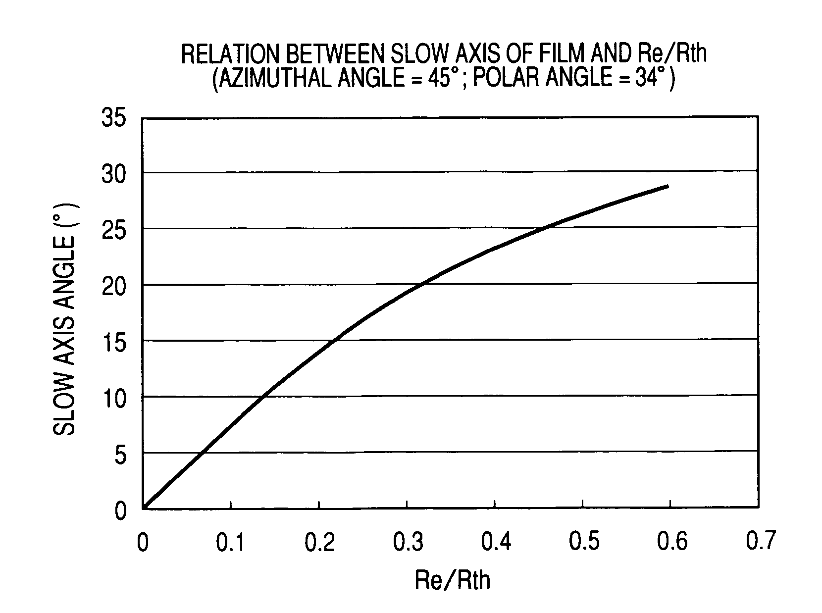
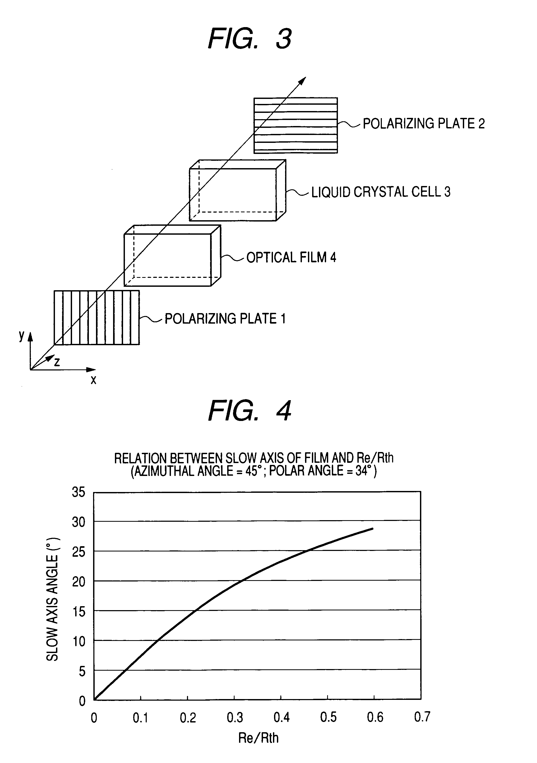
[0030]An aspect of the invention has been completed based on the findings obtained by the intensive investigation of the inventors, wherein wavelength distribution of in-plane retardation of an optical compensatory film and wavelength distribution in the thickness direction are independently controlled by, for example, selecting proper materials and a proper production process to determine its optically optimal value and ensure viewing angle compensation of a liquid crystal cell, particularly, a VA mode liquid crystal cell, giving a black display in almost all wavelength region. As a result, a liquid crystal display of the invention shows a reduced light leakage when obliquely viewed upon black display, thus viewing angle contrast being remarkably improved. Also, since a liquid crystal display of the invention can suppress light leakage when obliquely viewed upon black display in almost all visible light wavelength region, color shift upon black display depending upon viewing angle can markedly be suppressed. According to an aspect of the invention, there can be provided an optical film which has a high contrast ratio over a wide range and which can suppress color shift, and an optical compensatory film, a polarizing plate and a liquid crystal display using the same.

Problems solved by technology

However, liquid crystal displays for television use, which are supposed to be equipped with big screens and to be viewed from various angles, have stringent demands on viewing angle dependence, so even the foregoing art cannot satisfy such demands.
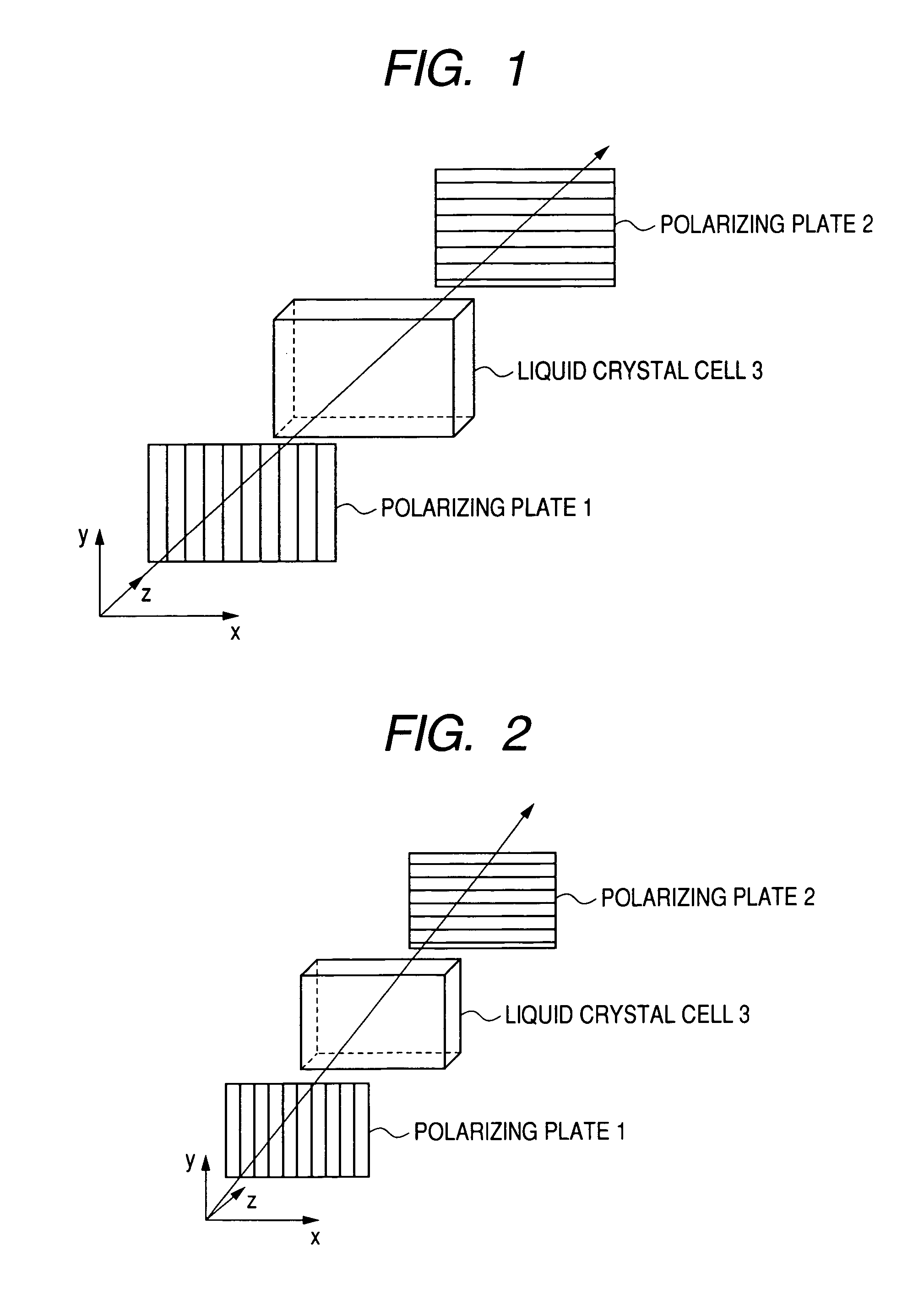
In VA mode, however, although almost complete black display can be given in the normal direction for a panel, light leakage generates when the panel is viewed from an oblique direction, thus the viewing angle becoming narrow.
However, these methods reduce light leakage only for a light of a certain wavelength region (for example, green light around 550 nm) and do not take into consideration light leakage for a light of other wavelength region (for example, blue light around 450 nm and red light around 650 nm).

Method used


Image

  • Optical film and optical compensatory film, polarizing plate and liquid crystal display using same
  • Optical film and optical compensatory film, polarizing plate and liquid crystal display using same
  • Optical film and optical compensatory film, polarizing plate and liquid crystal display using same

Examples


example 1

[0535]An aqueous solution of sodium hydroxide and ion-exchanged water were charged in a reactor equipped with a stirrer, a thermometer and a reflux condenser, and monomers (E) and (F) respectively having the above-described structures were dissolved therein with a molar ratio of 47:53, followed by adding thereto a small amount of hydrosulfite. Subsequently, methylene chloride was added thereto, and phosgene was blown thereinto at 20° C. in about 60 minutes. Further, p-tert-butylphenol was added thereto to emulsify, followed by adding thereto triethylamine and stirring the mixture at 30° C. for about 3 hours to complete the reaction. After completion of the reaction, the organic phase was separated, and inethylene chloride was distilled off to obtain a polycarbonate copolymer. The composition ratio of the resulting copolymer was almost the same as the ratio with charged monomers.

[0536]3 Parts of the following discotic compound per 100 parts by weight of the copolymer was dissolved in...

example 2

[0540]The same dope solution as used in Example 1 was used. This dope solution was continuously cast through a die onto a stainless steel-made band and was then peeled from the band at a residual solvent amount of 20% by weight, followed by free uniaxial stretching with a stretch ratio of 1.4 times the original in the longitudinal direction in a 200° C. drying zone between roll sets different from each other in rotation velocity. Further, the stretched film was passed through a drying zone where the residual solvent amount was reduced to 1% by weight or less to obtain an optical film having properties shown in Table 1.

example 3

[0542]A dope solution containing 18% by weight of solid components was prepared by dissolving in methylene chloride 3 parts by weight of the following rod-shaped compound in place of the discotic compound used in Example 1 per 100 parts by weight of the polycarbonate. This dope solution was continuously cast through a die onto a stainless steel-made band and was then peeled from the band at a residual solvent amount of 20% by weight, followed by free uniaxial stretching with a stretch ratio of 1.6 times the original in the longitudinal direction in a 200° C. drying zone between roll sets different from each other in rotation velocity. Further, the stretched film was passed through a drying zone where the residual solvent amount was reduced to 1% by weight or less to obtain an optical film having properties shown in Table 1.

[0543]


PUM

PropertyMeasurementUnit
mol %aaaaaaaaaa
mol %aaaaaaaaaa
wavelength regionaaaaaaaaaa

Abstract

An optical film is provided and contains at least one of a polycarbonate copolymer and a blend containing the polycarbonate copolymer. The polycarbonate copolymer contains specific repeating units. The optical film satisfies the following formulae (1) to (4).0.1<Re(450) / Re(550)<0.95  (1)1.03<Re(650) / Re(550)<1.93  (2)0.4<(Re(450) / Rth(450)) / (Re(550) / Rth(550))<0.95  (3)1.05<(Re(650) / Rth(650)) / (Re(550) / Rth(550))<1.90  (4)

Description

FIELD OF THE INVENTION[0001]The present invention relates to an optical film and an optical compensatory film, a polarizing plate and a liquid crystal display using the same.BACKGROUND OF THE INVENTION[0002]Liquid crystal displays are widely used in personal computers, mobile equipment monitors and televisions since they have various advantages, e.g., in their low voltage and low consumption power and high possibility for reduction in size and profile. Although a variety of modes depending on how liquid crystalline molecules are aligned in a liquid crystal cell have been proposed for such liquid crystal displays, the dominating mode has hitherto been a TN mode in which liquid crystalline molecules are in an aligned state that their orientations twist by about 90° toward an upper side substrate from a lower side substrate.[0003]In general a liquid crystal display is made up of a liquid crystal cell, an optical compensation film and a polarizer. The optical compensation film is used f...

Claims


Application Information

Patent Timeline
Patent Type & Authority Patents(United States)
IPC IPC(8): G02F1/13363
CPCC08J5/18G02F1/13363C08J2369/00G02F2001/133633Y10T428/105G02F2413/04Y10T428/1036Y10T428/10G02F2202/40Y10T428/31507C09K2323/035C09K2323/03C09K2323/00G02F1/133633
Inventor NAKAYAMA, HAJIMEOHASHI, YUSUKE
Owner FUJIFILM CORP
Why Eureka
Try Eureka