Method and apparatus for removing mercury from combustion exhaust gas

a technology of combustion exhaust gas and mercury removal, which is applied in the direction of antimony compounds, machines/engines, arsenic compounds, etc., can solve the problems of methylmercury being toxic to humans, affecting the health of people, and accumulating in the environment, so as to reduce mercury emissions and create turbulence

Inactive Publication Date: 2009-06-09
GENERAL ELECTRIC CO
View PDF28 Cites 35 Cited by
  • Summary
  • Abstract
  • Description
  • Claims
  • Application Information

AI Technical Summary

Problems solved by technology

Mercury deposited in the environment is a persistent and toxic pollutant that may accumulate in the food chain.
Methylmercury is toxic to humans and has been shown to cause disorders of the nervous system, comas, heart disease, and death.
Moreover, the adverse affects of methylmercury may be more severe to children and women of childbearing age.
The control of mercury emissions is complicated by the several forms mercury may take within combustion flue gas.
For example, at combustion temperatures, mercury is present in flue gas in its elemental form, Hg0, which may be difficult to control because elemental mercury is easily volatized and unreactive.
Because mercury can take several forms, known control technologies do not effectively control mercury emission for all coal types and for all combustion configurations.
As such, mercury removal through reactions with carbon-in-fly ash may not be effective because such fly ash does not have a sufficient amount of carbon with which the mercury can react.
However, the cost of using activated carbon for mercury control may be expensive, and as such, mercury emission control may be affected by cost of the sorbent.
Elemental mercury is more difficult to remove than oxidized mercury and / or particulate-bound mercury because elemental mercury is unreactive and, as such, cannot be removed from flue gas with wet desulfurization systems or particulate collection system.
In some known systems, because the concentration of mercury in the flue gas is very small (typically less than 10 parts per billion or ppb), diffusion of mercury from the surrounding flue gases may limit the mercury removal process.

Method used


Image

  • Method and apparatus for removing mercury from combustion exhaust gas
  • Method and apparatus for removing mercury from combustion exhaust gas

Examples


Embodiment Construction

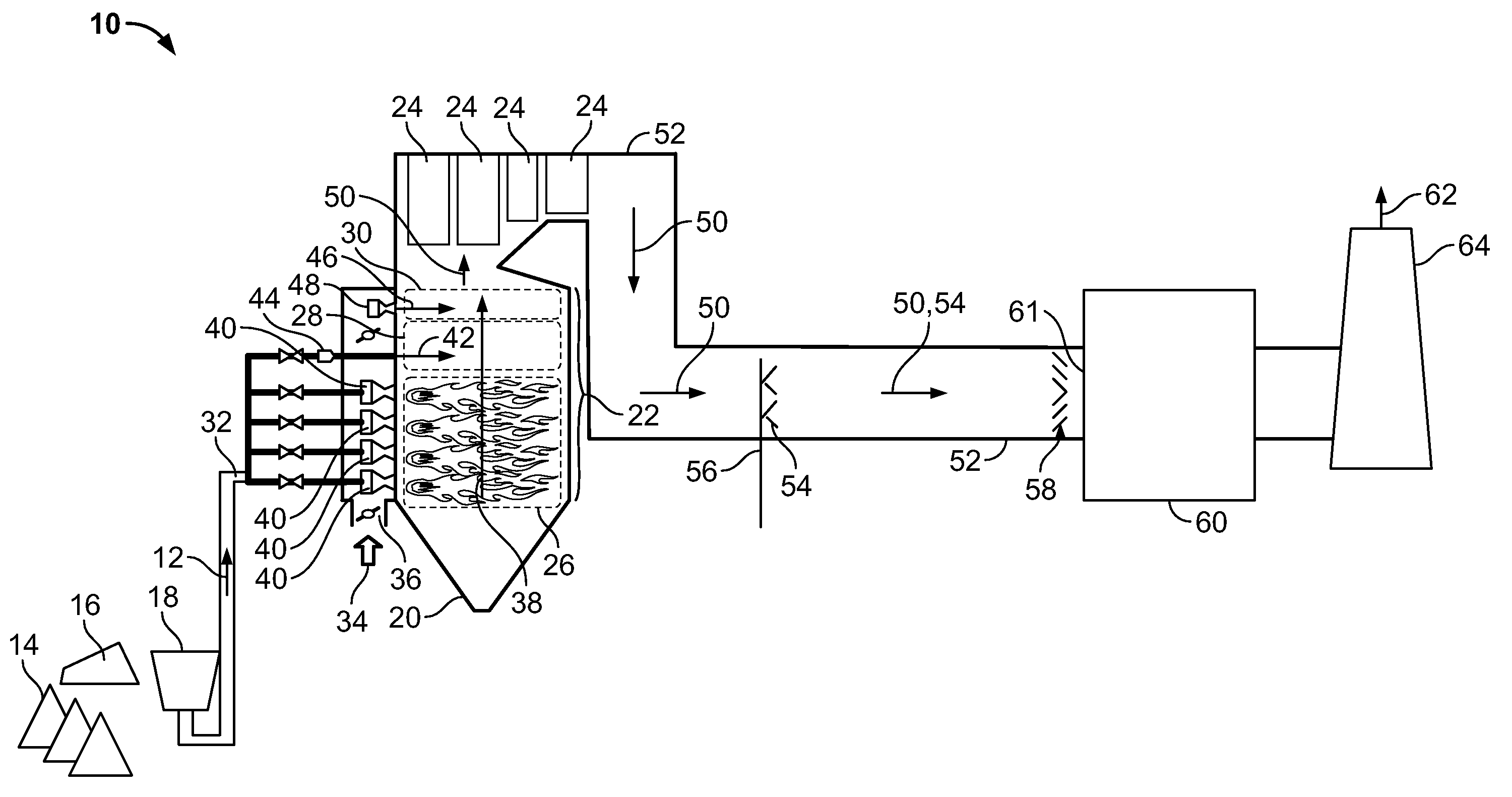
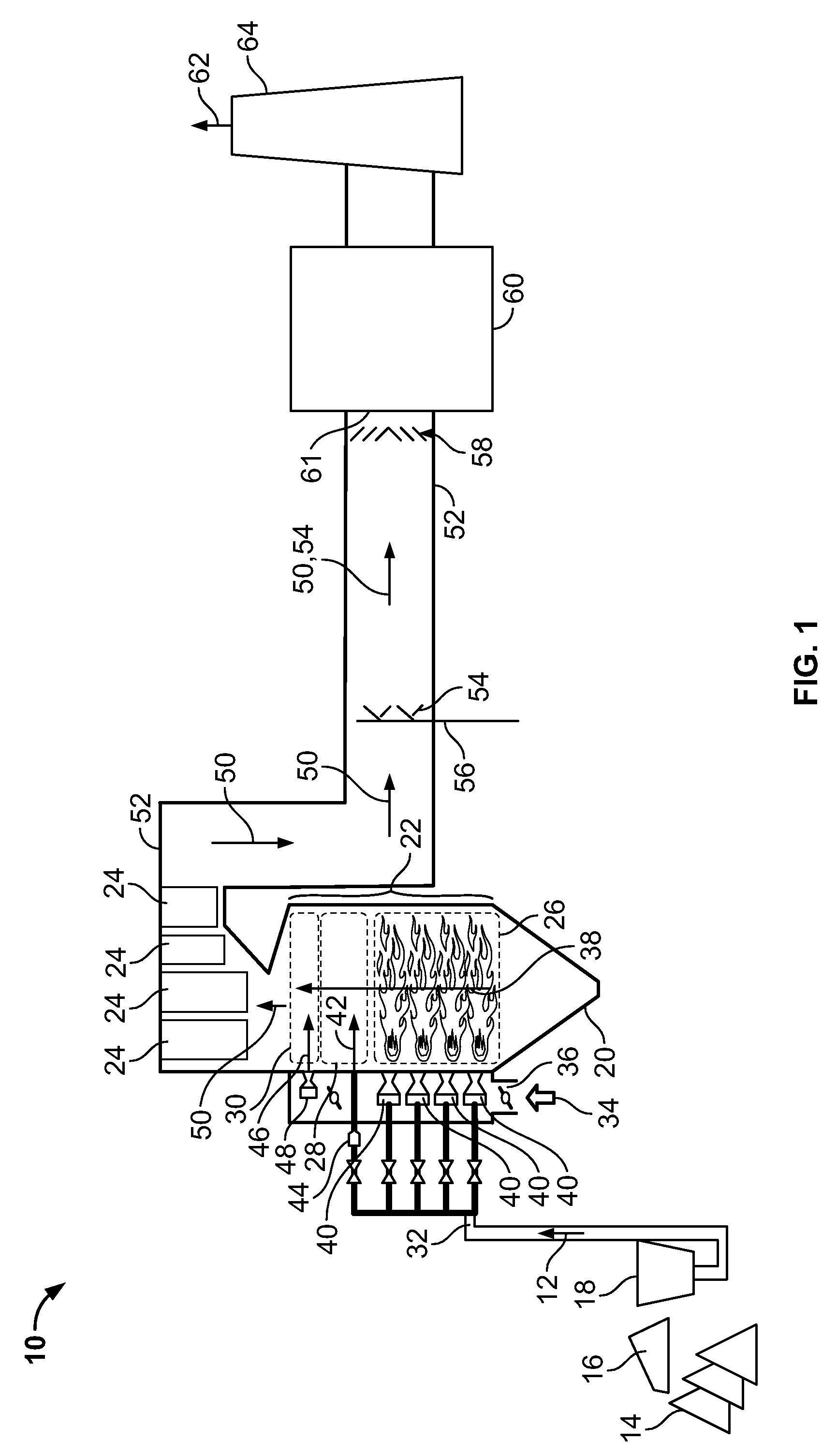
[0014]FIG. 1 is a schematic view of an exemplary power plant system 10. In the exemplary embodiment, system 10 is supplied with fuel 12 in the form of coal 14. More specifically, in the exemplary embodiment, the coal 14 is bituminous coal, such as, but not limited to, Powder River Basin (PRB) coal, lignite coal, and / or any other suitable coal that enables system 10 to function as described herein. Alternatively, fuel 12 may be any other suitable fuel, such as, but not limited to, oil, natural gas, biomass, waste, or any other fossil or renewable fuel. In the exemplary embodiment, coal 14 is supplied to system 10 from a coal supply 16 is processed in a coal mill 18. In the exemplary embodiment, coal 14 is pulverized in coal mill 18 to form coal particles (not shown) having a predetermined and selectable fineness.

[0015]In the exemplary embodiment, coal fineness is measured using a known sieve analysis method. Alternatively, coal fineness may be measured using any other suitable method...


PUM

PropertyMeasurementUnit
temperaturesaaaaaaaaaa
diameteraaaaaaaaaa
temperatureaaaaaaaaaa

Abstract

A method for reducing mercury emissions in combustion flue gas is provided. The method includes combusting coal such that a flue gas flow is created. The flue gas flow includes at least mercury and carbon-containing fly ash. The method further includes cooling the flue gas flow within a duct and creating turbulence in the flue gas flow. The mercury is removed from the flue gas flow.

Description

BACKGROUND OF THE INVENTION[0001]This invention relates generally to combustion devices and, more particularly, to emission control systems for combustion devices.[0002]During a typical combustion process within a furnace or boiler, for example, a flow of combustion gas, or flue gas, is produced. Known combustion gases contain combustion products including, but not limited to, carbon, fly ash, carbon dioxide, carbon monoxide, water, hydrogen, nitrogen, sulfur, chlorine, and / or mercury generated as a result of combusting solid and / or liquid fuels.[0003]The volatile metal mercury, Hg, is an air pollutant produced through coal combustion. Mercury released from coal during combustion is readily aerosolized and can become airborne. Airborne mercury may travel globally prior to being deposited into soil and water. Mercury deposited in the environment is a persistent and toxic pollutant that may accumulate in the food chain. For example, mercury can be transformed within microorganisms int...

Claims


Application Information

Patent Timeline
Patent Type & Authority Patents(United States)
IPC IPC(8): B01D53/64B01D53/74B01D53/83F01N13/16
CPCB01D53/64F23J15/006F23J15/022F23M9/003B01D53/10B01D53/323B01D2253/102B01D2257/602F23J2215/60F23J2217/101F23J2217/102F23J2217/20F23J2219/30F23J15/02
Inventor LISSIANSKI, VITALI VICTORMALY, PETER MARTINSEEKER, WILLIAM RANDALLTAYLOR, ROBERT WARREN
Owner GENERAL ELECTRIC CO
Why Eureka
Try Eureka