Apparatus and method for minimally invasive total joint replacement

a total joint replacement and minimally invasive technology, applied in the field of minimally invasive total joint replacement, can solve the problems of increasing pain, increasing pain, and affecting the healing effect of the joint, and achieves the effects of accurate bone preparation, minimally invasive surgical procedures, and limited surgical exposur

Inactive Publication Date: 2009-07-14
CAYENNE MEDICAL INC
View PDF8 Cites 13 Cited by
  • Summary
  • Abstract
  • Description
  • Claims
  • Application Information

AI Technical Summary

Benefits of technology

[0013]The present invention provides a system and method for total joint replacement that involves minimally invasive surgical procedures. The instruments disclosed accomplish accurate bone preparation through a limited surgical exposure.
[0016]Specifically, for example, the invention may be used for replacing the surfaces of a femur and acetabulum through a minimal incision and with minimal disruption of musculotendinous structures about the hip. A typical incision for a minimally invasive total hip procedure is between two and four inches in length. It is noted that there may be some variation in incision length due to patient physiology, surgeon preferences, and / or other factors; the stated range is illustrative, not limiting. In addition to a small incision, care is taken to approach the joint capsule by separating tissues between muscle groups, rather than sectioning specific muscles. The invention includes, in various embodiments, a reamer system. The reamer system in accordance with the present invention is either a modular or non-modular construct that, for hip applications, comprises a femoral attachment component which is typically a femoral trial, a reamer drive (either integral or separate), a handle, and a hemispherical grater or similar device for removing cartilage and bone from the acetabular fossa. The reamer system is powered by a power source such as a standard surgical drill. Optionally, the reamer system may be powered by an integral power source such as an electric, pneumatic or hydraulic motor, a solenoid, an electromechanical drive or other suitable power source. The reamer system is designed or structured to be placed into the joint cavity via one or more small incisions while leaving most, if not all, muscles intact. Surgical navigation may be used to aid in positioning the reamer system and in monitoring progression of acetabular preparation by attaching a navigational tracker to the pelvis and a second navigational tracker to the reamer drive. Optionally, the second navigational tracker may be attached to the handle. Once the femur and acetabulum have been prepared, the implants are placed without further muscle release or surgical trauma.

Problems solved by technology

The articular surfaces of the bony structures may become damaged by a variety of diseases, accidents, and other causes.
Degenerative arthritis causes progressive pain, swelling, and stiffness of the joints.
Moreover, progression of the disease process increases pain and reduces mobility.
While drug therapies may temporarily provide relief of pain, progression of the disease, with resulting deformity and reduced function, ultimately necessitates surgery.
A difficulty with total hip replacement is that the invasiveness of the procedure causes significant intraoperative blood loss and extensive rehabilitation because muscles and tendons must be released from the proximal femur to mobilize the femur and gain exposure of and access to the acetabular fossa.
The surgical exposure, which may be between six and twelve inches in length, may result in extensive trauma to the soft tissues surrounding the hip joint along with the release of muscles that insert into the proximal femur.
However, soft tissue structures limited proper orientation of these devices leading to the development of curved drive handles used to avoid soft tissue interference.
In addition, such devices still required retraction of the proximal femur to provide access for the handle and grater to the acetabulum.
Extensive distraction force is needed to displace the femur resulting in trauma to soft tissue structures because of the magnitude and duration of the force imparted.
As with the straight and curved drive handles described above, a pivotable head drive handle interferes with soft tissue structures while preparing the acetabulum and requires distraction of the femur to allow access to the acetabulum.

Method used


Image

  • Apparatus and method for minimally invasive total joint replacement
  • Apparatus and method for minimally invasive total joint replacement
  • Apparatus and method for minimally invasive total joint replacement

Examples


Embodiment Construction

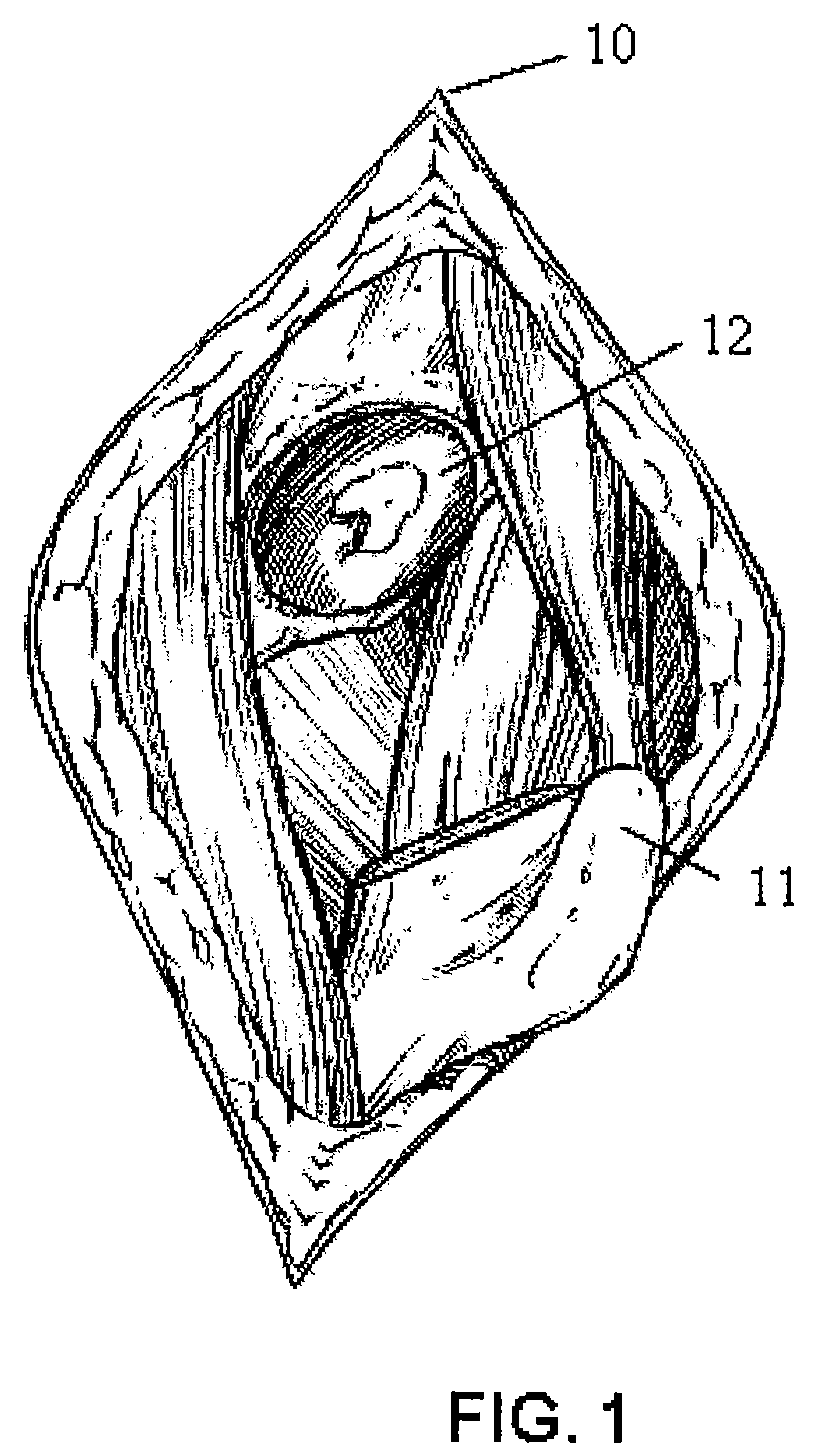
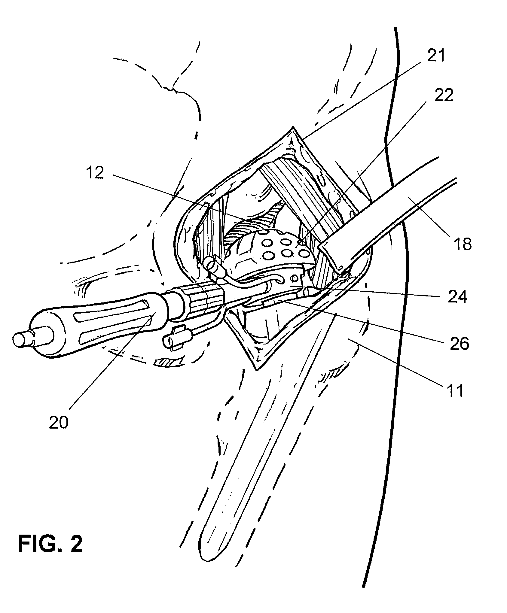
[0030]FIG. 1 illustrates the general anatomy of a hip joint and a typical surgical approach 10 to the hip joint to expose a proximal femur 11 and an acetabulum 12. Four surgical approaches to the hip joint for total hip replacement are known. These approaches include posterior approaches without trochanteric osteotomy, trans-trochanteric approaches, anterior approaches without trochanteric osteotomy, and Smith-Peterson approaches. A direct lateral approach is also known for total hip arthroplasty. The most common surgical approach to the hip is posterior, and the musculature disrupted may include the short internal and external rotators, tensor fascia femoris, quadratus femoris, piriformis, and on occasion part of the gluteus medius and minimus, and the gluteus maximus.

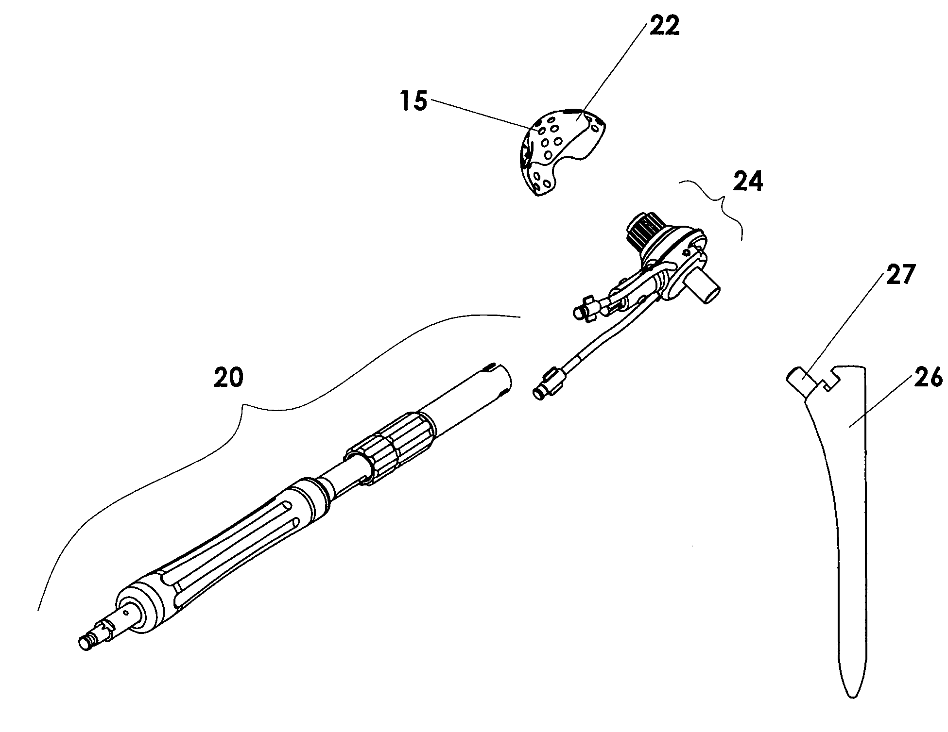
[0031]In conventional total hip replacement surgery the hip joint is exposed through a large incision to provide the surgeon full visualization of the hip joint and the acetabular region, and to provide access for sur...


PUM


Abstract

A method and apparatus for minimally invasive total joint replacement is disclosed. The method involves sculpting the articular surface of a second bone that normally articulates with a first bone by attaching or supporting a bone sculpting tool directly or indirectly to the first bone with the tool in sculpting engagement with the articular surface of the second bone, and then sculpting the articular surface of the second bone with the joint reduced. The reamer system includes a reamer drive, a grater, a handle and a femoral broach.

Description

CROSS REFERENCE TO RELATED APPLICATIONS[0001]This application is a continuation-in-part and claims the benefit of U.S. provisional patent application Ser. No. 60 / 721,450 filed Sep. 28, 2005, which is a continuation-in-part of U.S. patent application Ser. No. 10 / 429,435 filed May 5, 2003, which is a divisional of U.S. patent application Ser. No. 10 / 075,829 filed Feb. 12, 2002 now U.S. Pat. No. 6,723,102, the entireties of which are hereby incorporated by reference.BACKGROUND OF THE INVENTION[0002]A joint generally consists of two relatively rigid bony structures that maintain a relationship with each other. Soft tissue structures spanning the bony structures hold the bony structures together and aid in defining the motion of one bony structure relative to the other. Soft tissue such as ligaments, tendons, menisci, and capsule provide support to the bony structures. A smooth and resilient surface consisting of articular cartilage covers the bony structures. The articular surfaces of t...

Claims


Application Information

Patent Timeline
Patent Type & Authority Patents(United States)
IPC IPC(8): A61B17/00
CPCA61B17/1666A61B17/1746A61B2019/508A61B2017/0046A61B2017/00535A61B19/5244A61B34/20A61B2034/108
Inventor JOHNSON, WESLEY D.ENGH, GERARD A.TRAVANTY, MIKE
Owner CAYENNE MEDICAL INC
Why Eureka
Try Eureka