Liquid crystal display device

a display device and liquid crystal technology, applied in liquid crystal compositions, instruments, chemistry apparatus and processes, etc., can solve the problems of limiting the application of dynamic picture displays used for television, increasing the cost of declining yields, and poor display qualities

Active Publication Date: 2009-08-18
JAPAN SCI & TECH CORP
View PDF2 Cites 85 Cited by
  • Summary
  • Abstract
  • Description
  • Claims
  • Application Information

AI Technical Summary

Benefits of technology

[0011]The present invention is a liquid crystal display device that deals with an in-place switching (IPS) mode and presents a liquid crystal display device that does not require a surface orientation treatment and can dramatically improve the response rate that, in conventional liquid crystal displays, is inadequate for use in dynamic picture displays. In addition, when a polymer-stabilized blue phase liquid crystal (BP) is used as an LCD element, the selective reflection in the visible light wavelength zone caused by the BP structure is the reason for light leakage when the display is black. Therefore, the present invention provides a liquid crystal display device that has no light leakage from a black screen, which means to yield a dark screen.Means to Solve the Problems
[0013]The liquid crystal display device of the present invention is suitable for creating larger and better quality liquid crystal screens used in an in-place switching (IPS) mode. In addition, no surface orientation treatment used for orientation control is necessary since polymer-stabilized blue phase liquid crystals are used. Therefore, the orientation treatment-washing-drying process such as coating-drying-heat curing-rubbing and the like of an oriented film on a substrate surface that used to be essential in conventional display devices can be completely eliminated. In addition, foreign material contamination caused by dust, fine particles and the like associated with the process described above, static electricity generation and declines in yield and quality caused by scratching can be avoided by this process. The response time of the conventional liquid crystal display devices was basically limited since the basic theory focused on the changes in the orientation state of nematic liquid crystals, and the dynamic picture display function of such elements was worse than that of plasma panels and EL, the competing technologies. However, a polymer-stabilized blue phase solved this problem since a response time in the order of about one hundred microseconds was possible.
[0014]In addition, by optimizing the type and amount of the chiral dopant added to liquid crystals, the diffraction wavelength of the liquid crystals can be controlled to the zone outside the visible light zone (from 380 nm to 750 nm). As a result, the liquid crystal display devices using such polymer-stabilized blue phase liquid crystals can avoid light leakage during black displays, which means to yield a dark visual field.

Problems solved by technology

The rubbing treatment is an operation in which a cloth or the like is used to rub an orientation membrane that has been surface coated onto a substrate surface and is in contact with liquid crystals, and is the cause of increased costs associated with declining yields and poorer display qualities.
In addition, all of the modes described above use nematic liquid crystals, and their response times are about ten milliseconds at the shortest, thus limiting their application in dynamic picture displays used for television.

Method used


Image

  • Liquid crystal display device
  • Liquid crystal display device
  • Liquid crystal display device

Examples


example 1

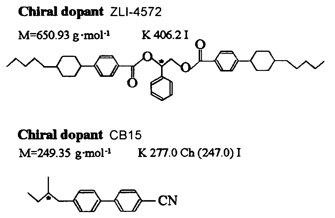
[0055]JC1041-XX (Chisso), a fluorinated liquid crystal blend used as the liquid crystal, 4-cyano-4′-pentylbiphenyl (5CB) (Aldrich) and ZLI-4572 (Merck) used as a chiral agent were mixed and heated. The individual proportions were 47.2 / 47.2 / 5.6 (% by mole) as shown in the table below. Monofunctional 2-ethylhexyl acrylate (EHA) (Aldrich) and difunctional RM257 (Merck) photo polymerizable monomers were added to the mixed solution to form a polymer network in the mixed solution. The monomer composition ratio was EHA / RM257=70 / 30 (% by mole). Furthermore, 2,2-dimethoxyphenylacetophenone (DMPAP) (Aldrich) was added as the photo polymerization initiator to obtain a uniform solution. The monomer concentration in the mixed solution was referred to as α, and the α was varied from 4 mole % to 15 mole %. The DMPAP was prepared so that it was present at 5% by mole based on the monomer mixture.

[0056]

TABLE 1MonomerPhotoinitiatorLiquid CrystalSampleEHARM257DMPAPJC1041-XX5CBZLI-4572Molar ratio / mol %7...

example 2

[0063]In order to control the diffraction wavelength of the BP that appeared to 380 nm or lower, a chiral agent CB15 (Aldrich) was introduced into a mixed liquid crystal (JC1041-XX / 5CB / ZLI-4572). The composition of each (photo polymerizable monomer / liquid crystal) composite sample prepared is shown in Table 2.

[0064]

TABLE 2MonomerPhotoinitiatorLiquid CrystalSampleEHARM257DMPAPJC1041-XX5CBZLI-572CB15Molar ratio / mol %703037.237.25.620Composite6.5 mol %0.33 mol %93.2 mol %

[0065]The temperature dependence of the reflection spectrum for a (photo polymerizable monomer / liquid crystal) composite system is shown in FIG. 7. In order to prevent the initiation of photo polymerizable monomer polymerization by the examination light source (365 nm), the scanned wavelength zone was from 700 nm to 375 nm. The reflection spectrum clearly indicated that the BP appearance temperature range for the composite system was about 2.5° K.

[0066]The inserted figures in FIG. 7 were polarized light microscope imag...


PUM

PropertyMeasurementUnit
diffraction wavelengthaaaaaaaaaa
response timeaaaaaaaaaa
distanceaaaaaaaaaa

Abstract

Presents a liquid crystal display device that does not require a surface orientation treatment, dramatically improves the response rate of dynamic image displays and does not experience light leaks when the display is black, which means to yield a dark field of vision. The liquid crystal display device comprises polymer-stabilized blue phase liquid crystals sandwiched between a pair of clear substrates. The liquid crystal display device obtained using polymer-stabilized blue phase liquid crystals exhibits large double refraction changes when an electrical field is applied in an in-plane direction to the cell substrates. The polymer-stabilized blue phases liquid crystals comprises a low molecular weight liquid crystal that allows a blue phase to appear between cholesteric and isotropic phases and polymer network formed in the low molecular weight liquid crystals. Furthermore, a liquid crystal display device that does not leak light when the display is black (yields a dark field of vision) can be obtained by optimizing the type and amount of a chiral dopant added to the liquid crystals.

Description

FIELD OF THE INVENTION[0001]The present invention relates to a liquid crystal display device using polymer-stabilized blue phase liquid crystals in an in-plane switching (IPS) mode.PRIOR ART[0002]Liquid crystal display devices are widely used in the optical data processing field. The conventional liquid display modes include TN, STN, IPS, VA (MVA), OCB and the like. All of these modes cause the liquid crystal molecular orientation already under control to change into a different state of orientation when electrical fields are applied and change the polarization direction and polarization state of the transmitted light. The changes are converted into light and dark contrasts in polarized boards and the like to generally form a display.[0003]These conventional liquid crystal display modes all require a surface orientation treatment in order to control the liquid crystal molecular orientation. A rubbing treatment is needed with the particular exception of VA (MVA). The rubbing treatmen...

Claims


Application Information

Patent Timeline
Patent Type & Authority Patents(United States)
IPC IPC(8): C09K19/02C09K19/54C09K19/58G02F1/13G02F1/1334G02F1/1343G02F1/137
CPCC09K19/02C09K19/0275C09K19/544C09K19/586G02F1/13718G02F2001/13793G02F1/134363G02F2001/13775C09K2019/546G02F1/13775G02F1/13793G02F1/137
Inventor KIKUCHI, HIROTSUGUKAJIYAMA, TISATONAGAMURA, TOSHIHIKOHISAKADO, YOSHIAKI
Owner JAPAN SCI & TECH CORP
Why Eureka
Try Eureka