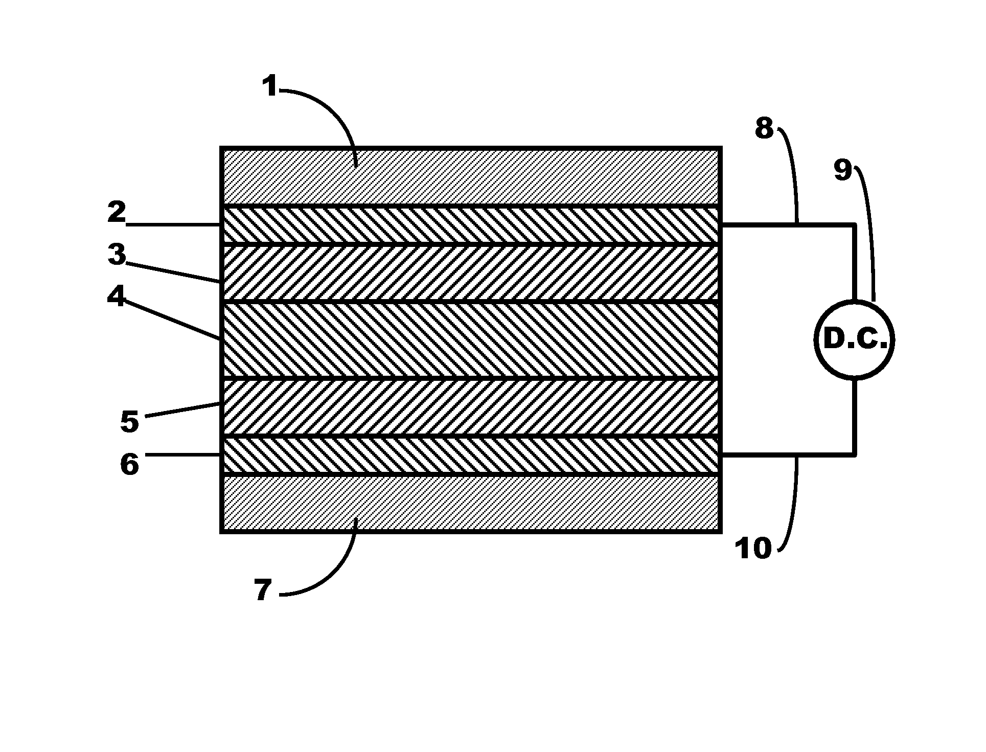
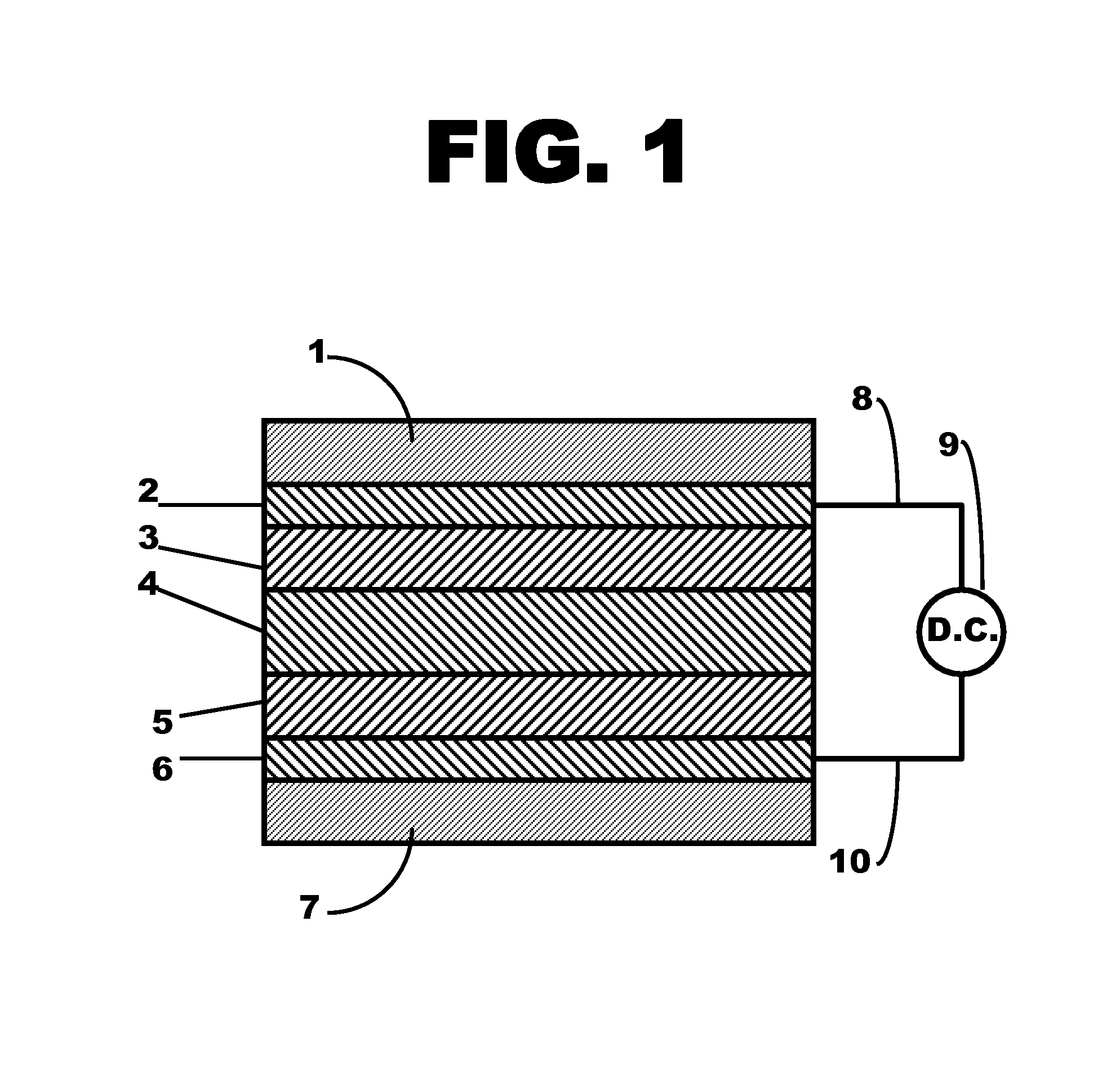
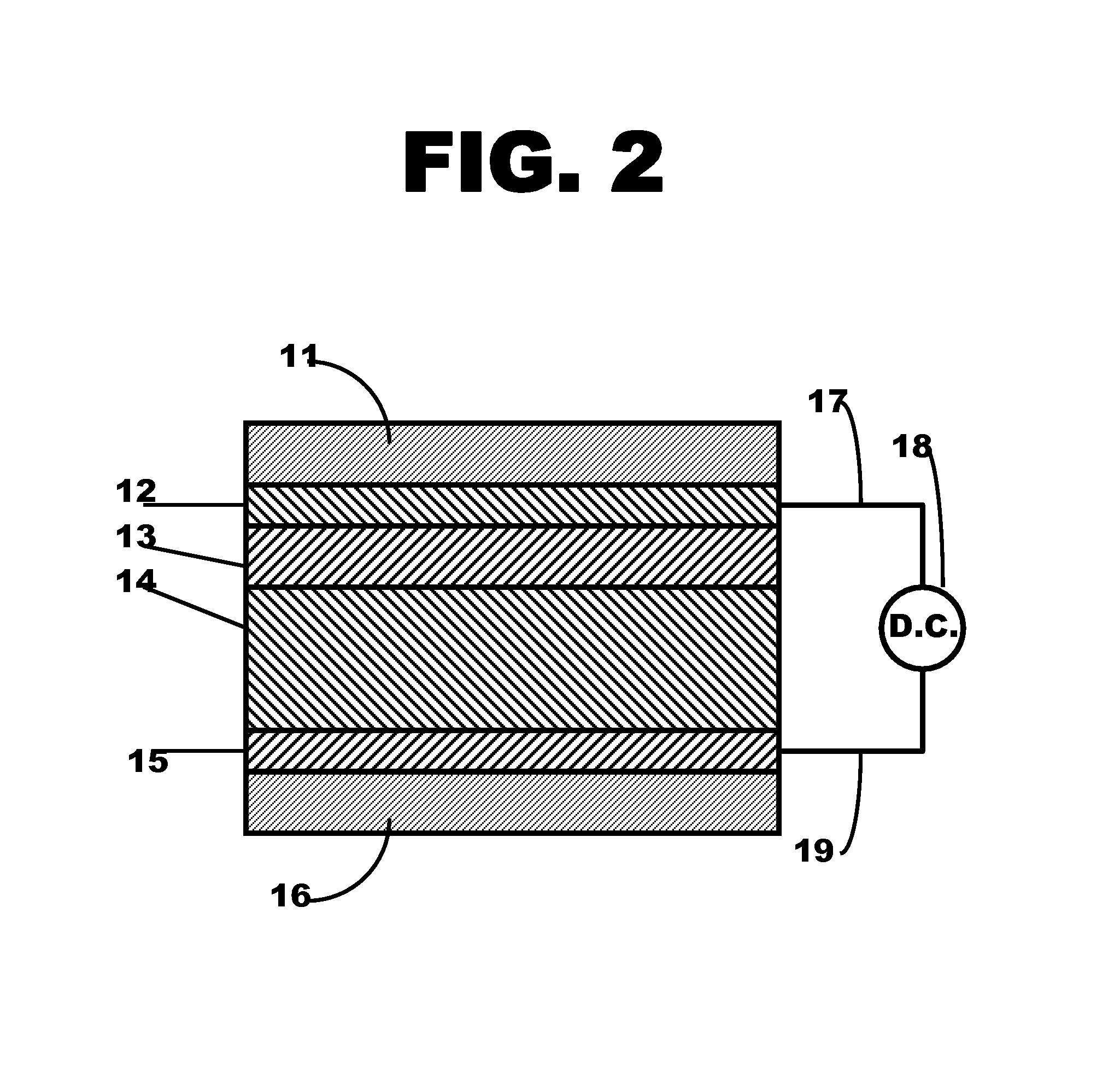
Metal ferrocyanide-polymer composite layer within a flexible electrochromic device
a technology of metal ferrocyanide and polymer, which is applied in the direction of instruments, non-linear optics, optics, etc., can solve the problems of incompatibility of deposition methods and high-speed roll-to-roll processing, and the existing methods of coating metal ferrocyanide on conductive plastic substrates require improvement, and achieve the effect of light weigh
- Summary
- Abstract
- Description
- Claims
- Application Information
AI Technical Summary
Benefits of technology
Problems solved by technology
Method used
Image
Examples
example 1
[0039]Example 1 demonstrates the synthesis of electrochromic polymer composites containing metal ferrocyanide particles with average particle sizes greater than about one micron. Such composites show poor transparency and poor color contrast on cycling.
[0040]The electrochromic layer was prepared in the following manner: A 4 wt % aqueous polyvinyl alcohol solution was prepared by mixing 1 g of polyvinyl alcohol (Scientific Polymer Products, 99% hydrolyzed, AVG MW ca 86,000) into 24 g of distilled water with heating and stirring. Into an 8 mL vial was measured 2 g of the 4 wt % aqueous polyvinyl alcohol solution and 0.08 g of iron(III) ferrocyanide, Fe4[Fe(CN)6]3 (insoluble Prussian Blue, Aldrich Chemical company, average particle size >1 micron). The vial was rotated at 4 RPM for 10 minutes to disperse the solids. The vial was then sonicated at room temperature for 1 hour in an ultrasonic bath. During sonication, the dispersion changed in color from black to deep blue.
[0041]Using the...
example 2
[0049]Example 2 demonstrates the usefulness of sub-micron iron (III) ferrocyanide particles, and the utility of perfluorosulfonated anionic polyelectrolyte in the electrochromic polymer composite.
[0050]The electrochromic layer coating solution was prepared in the following manner: Into a tall 180 mL beaker equipped with a stirring bar was measured 14.5 g of distilled water, 0.12 g of iron(III) chloride hexahydrate (Aldrich, reagent grade) and 0.10 g of potassium ferricyanide(III) (Aldrich, reagent grade). With vigorous stirring, to this solution was added dropwise 4.0 g of aqueous 7.5 wt % H2O2. The solution immediately turned blue, indicating the formation of an iron (III) ferrocyanide dispersion. The dispersion stirred for 15 minutes to complete the reaction. To this was added 125 g of distilled water, which virtually filled the beaker, to wash the iron (III) ferrocyanide. The beaker was then allowed to stand for 20 days to allow the iron (III) ferrocyanide to settle and concentra...
example 3
[0058]Example 3 demonstrates the utility of polyethylene oxide in the electrochromic polymer composite, and a more convenient method of making a composite with sub-micron iron (III) ferrocyanide particles. It also demonstrates the replacement of water in the dispersion with alcohol.
[0059]The electrochromic layer coating solution was prepared in the following manner: Into a tall 180 mL beaker equipped with a stirring bar was measured 70 g of distilled water and 0.05 g of polyethylene oxide (Aldrich, AVG MW 300,000). The solution was stirred for about 15 minutes to dissolve the polymer. To this was then added 0.10 g of potassium ferricyanide (III), and about 0.3 mL of aqueous 1% hydrogen peroxide solution.
[0060]Into a 100 mL beaker was measured 70 g of distilled water and 0.05 g of polyethylene oxide. The solution was stirred for about 15 minutes to dissolve the polymer. To this was then added 0.12 g of iron (III) chloride hexahydrate, and about 0.3 mL of aqueous 1% hydrogen peroxide ...
PUM
| Property | Measurement | Unit |
|---|---|---|
| particle size | aaaaa | aaaaa |
| particle sizes | aaaaa | aaaaa |
| particle size | aaaaa | aaaaa |
Abstract
Description
Claims
Application Information
 - R&D
- Intellectual Property
- Life Sciences
- Materials
- Tech Scout
- Unparalleled Data Quality
- Higher Quality Content
- 60% Fewer Hallucinations
Browse by: Latest US Patents, China's latest patents, Technical Efficacy Thesaurus, Application Domain, Technology Topic, Popular Technical Reports.
© 2025 PatSnap. All rights reserved.Legal|Privacy policy|Modern Slavery Act Transparency Statement|Sitemap|About US| Contact US: help@patsnap.com


