Electronically commutated motor and control system

Inactive Publication Date: 2009-10-13
BLACK & DECKER INC
View PDF6 Cites 45 Cited by
  • Summary
  • Abstract
  • Description
  • Claims
  • Application Information

AI Technical Summary

Benefits of technology

[0016]The motor of the present disclosure also makes use of a rotor having a construction that provides the benefits of surface mounted permanent magnets without the traditional performance drawbacks of a surface mounted magnet construction. The rotor includes a plurality of spaced apart pockets or recesses formed in an outer surface of a back iron of the rotor. The recesses are shaped to accommodate a plurality of arcuate shaped permanent magnets. The magnets have a thickness that permits them to rest with their outer arcuate surfaces generally flush with portions of the outer surface of the back iron. A retaining sleeve may be secured over, or formed over, the magnets and the back iron to encapsulate the magnets and hold them securely in their respective recesses in the back iron. The arcuate shaped magnets enable a uniform air gap to be maintained between the rotor and an inner surface of the stator. This provides increased flux output and greater power from a motor incorporating the rotor. This construction also provides improved robustness and excellent retention of the magnets, making the rotor well suited for use in high speed motors. The rotor can be readily implemented in a motor with a less complex controller than what would otherwise be required with a conventional rotor having

Problems solved by technology

However, designing the motor for high power applications is inefficient, from a power standpoint, if the same drill will frequently be used with tasks that involve only light duty drilling, where only low torque is needed for the work task.
The surface mounted rotor construction is not as well suited for use with motors that will be operated over a wide operati

Method used


Image

  • Electronically commutated motor and control system
  • Electronically commutated motor and control system
  • Electronically commutated motor and control system

Examples


Example

[0064]The following description of various embodiment(s) and methods is merely exemplary in nature and is in no way intended to limit the present disclosure, its application, or uses.

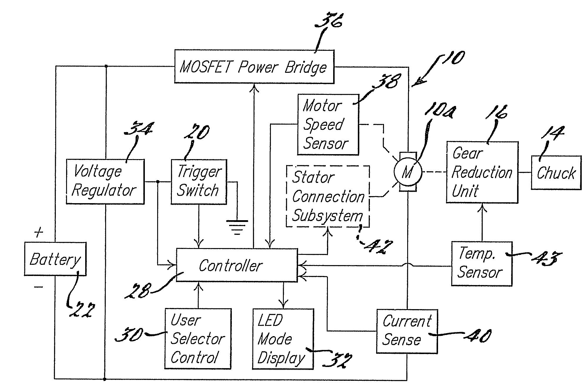
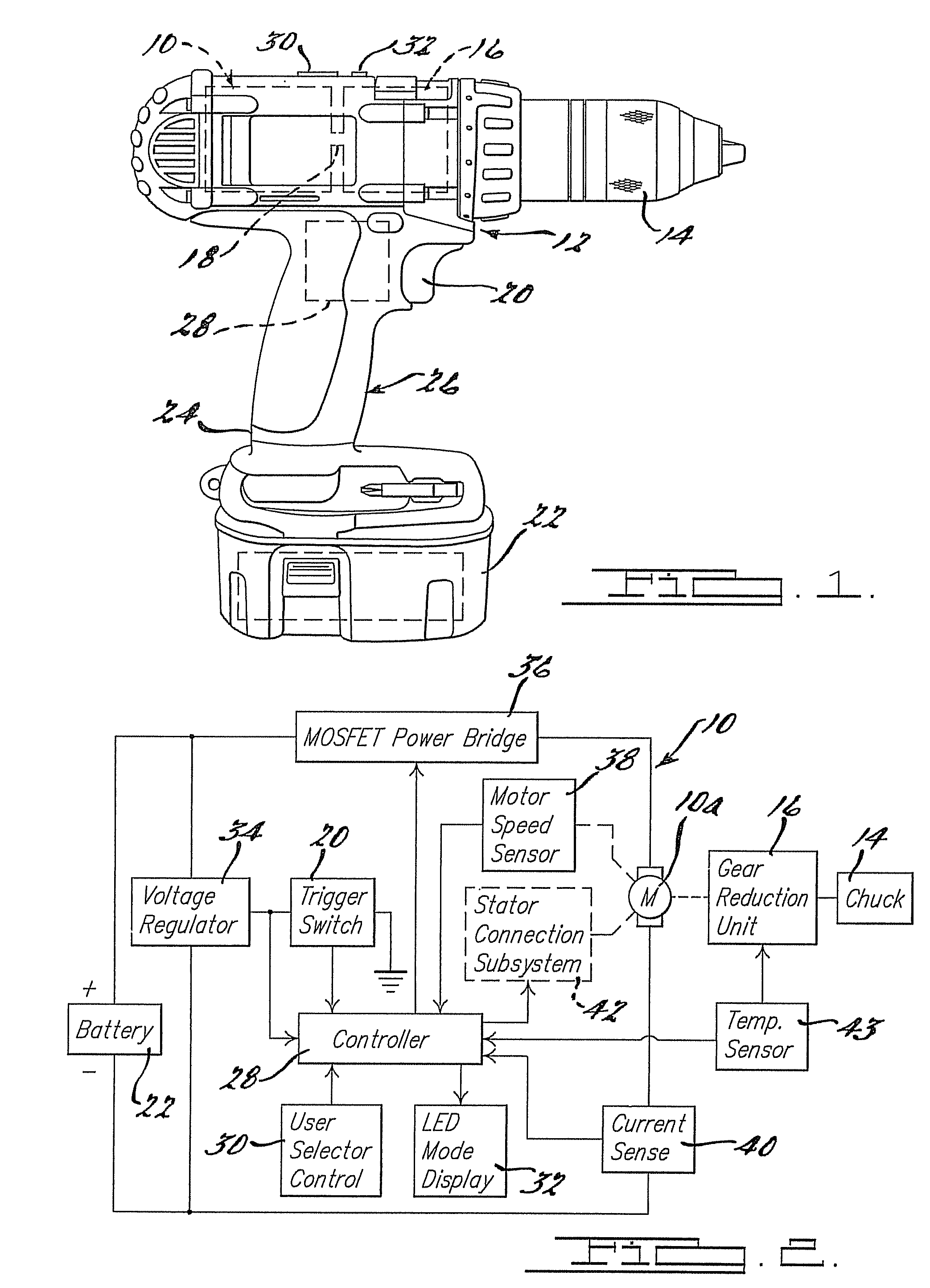
[0065]Referring to FIG. 1, a power tool in the form of a drill 12 incorporating a motor system 10 in accordance with an embodiment of the present disclosure is shown. It will be appreciated immediately that while the power tool is illustrated as a drill 12, that the motor system 10 can be implemented in a wide variety of other power tools such as saws, sanders, routers, and virtually any other form of DC powered tool or device. The motor system 10, however, is expected to find particular utility with cordless power tools.

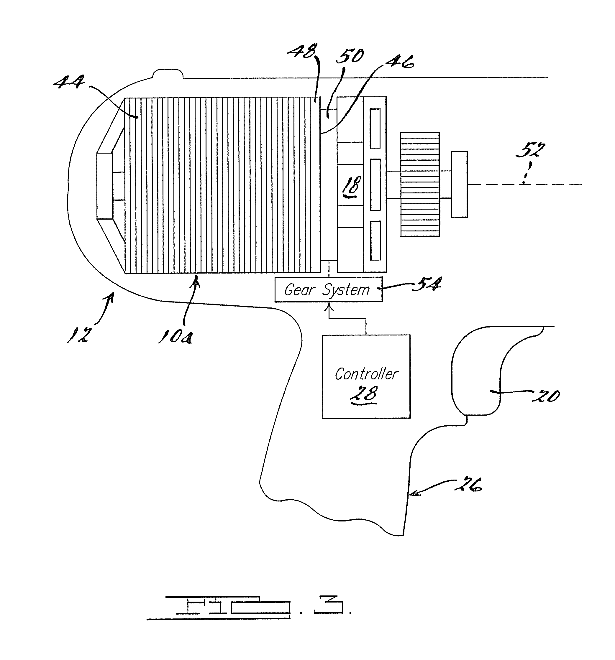
[0066]Referring further to FIG. 1, the exemplary drill 12 typically includes a chuck 14 coupled to an output of a gear reduction unit 16. An input of the gear reduction unit 16 is coupled to an output shaft 18 of an electronically commutated motor 10a of the system 10. A trigger 20 is u...


PUM


Abstract

A power tool having an electronically commutated DC motor capable of providing various operating modes ranging from a maximum efficiency operating mode to a maximum power operating mode. The motor has a rotor having permanent magnets mounted in recesses in a back iron of the rotor. In one embodiment the motor has three phase windings, each having at least a pair of coils. The phase windings are connected in either a delta or a wye configuration via electromechanical or electronic switching components, or a combination of both, by a controller within the tool. The coils in each phase winding can also be switched between series and parallel configurations to configure the motor to provide its various operating modes. In one embodiment a dual wound motor is disclosed that has its phase coils dynamically or statically switchable between series and parallel configurations.

Description

CROSS-REFERENCE TO RELATED APPLICATIONS[0001]The present application claims priority from U.S. provisional patent application Ser. No. 60 / 775,408, entitled “Electronically Commutated Motor And Control System”, filed Feb. 20, 2006, and is also related in general subject matter to U.S. provisional patent application Ser. No. 60 / 775,407, entitled “DC Motor with Dual Commutator Bar Set and Selectable Series and Parallel Connected Coils”, filed Feb. 20, 2006. The disclosures of both of the above mentioned provisional applications are hereby incorporated by reference into the present application.FIELD[0002]The present disclosure relates to electric motors, and more particularly to an electronically commutated motor having a plurality of operating modes that provide an operator of a tool in which the motor is used with a plurality of motor performance characteristics to suit widely varying work tasks with which the power tool is used. The present disclosure also relates to a new rotor desi...

Claims


Application Information

Patent Timeline
IPC IPC(8): H02P1/26
CPCH02K1/278H02K3/28H02K5/225H02K7/116H02P25/18H02K11/0063H02K11/0073H02P6/001H02K7/145H02K11/28H02K11/33H02P6/34H02P29/40
Inventor DU, HUNG T.DESHPANDE, UDAY S.WEST, JOSHUA D.GORTI, BHANUPRASAD V.WAIKAR, SHAILESH
Owner BLACK & DECKER INC
Why Eureka
Try Eureka