Electro optical scanning multi-function antenna

a multi-functional, electro optical scanning technology, applied in the direction of antennas, electrical equipment, electromagnetic transmission, etc., can solve the problems of high cost, high cost, and inability to meet the requirements of variable phase networks, which are not currently known antennas,

Inactive Publication Date: 2009-10-27
UNITED STATES OF AMERICA THE AS REPRESENTED BY THE SEC OF THE ARMY
View PDF17 Cites 20 Cited by
  • Summary
  • Abstract
  • Description
  • Claims
  • Application Information

AI Technical Summary

Benefits of technology

[0023]In operation, the control circuit, by varying the wavelength of the lasers, simultaneously controls the precise time delay of the optical wavelength-dependent time delay element associated with that tunable laser. Each photodetector, working within its linear range, will generate two RF signals of different frequency that have time delay sequences independent to each other for the two RF signals. This, in turn, simultaneously controls the direction of the radiated beam from the broadside beam di

Problems solved by technology

These previously known antennas, however, have not proven wholly satisfactory in operation.
One disadvantage of utilizing variable phase networks to control the beam direction for the phased antenna array is that the variable phase networks are expensive and this expense increases dramatically as the number of antenna radiators increases.
A still further disadvantage of these previously known variable phase networks is that the previously known systems have utilized switches to selectively connect transmission line sections between the signal input to the antenna and the various antenna radiators.
Furthermore, the signal losses associated with these switches are unacceptable for many high frequency applications, i.e. applications where the wavelength is in the millimeter range, such as 35 GHz.
A still further disadvantage of these previously known variable phase networks is that the circuitry necessary to affect the variable phase, particularly when a high number of antenna radiat

Method used


Image

  • Electro optical scanning multi-function antenna
  • Electro optical scanning multi-function antenna
  • Electro optical scanning multi-function antenna

Examples


Embodiment Construction

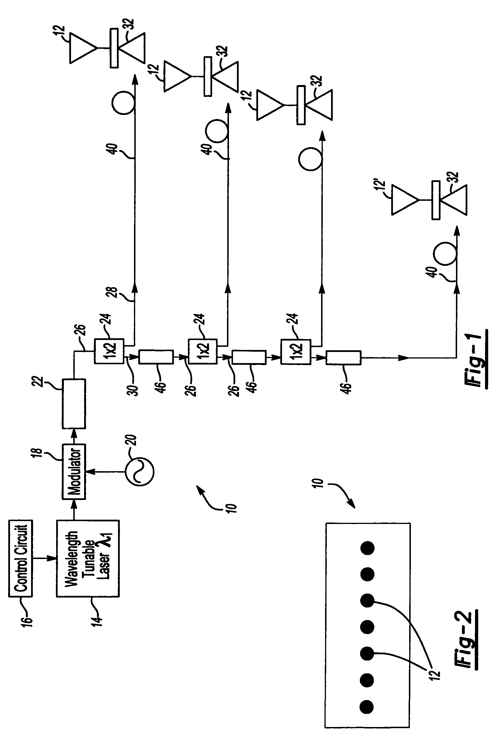
[0028]With reference first to FIG. 2, a plan view of an exemplary electro optical scanning antenna array 10 is illustrated as having a plurality of antenna radiators 12. The antenna radiators 12 are linearly aligned with each other and are preferably equidistantly spaced from each other. Although the antenna array 10 illustrated in FIG. 2 depicts seven antenna radiators 12, it will be understood that fewer or more antenna radiators 12 may be utilized in the array 10 without deviation from either the spirit or scope of the invention.

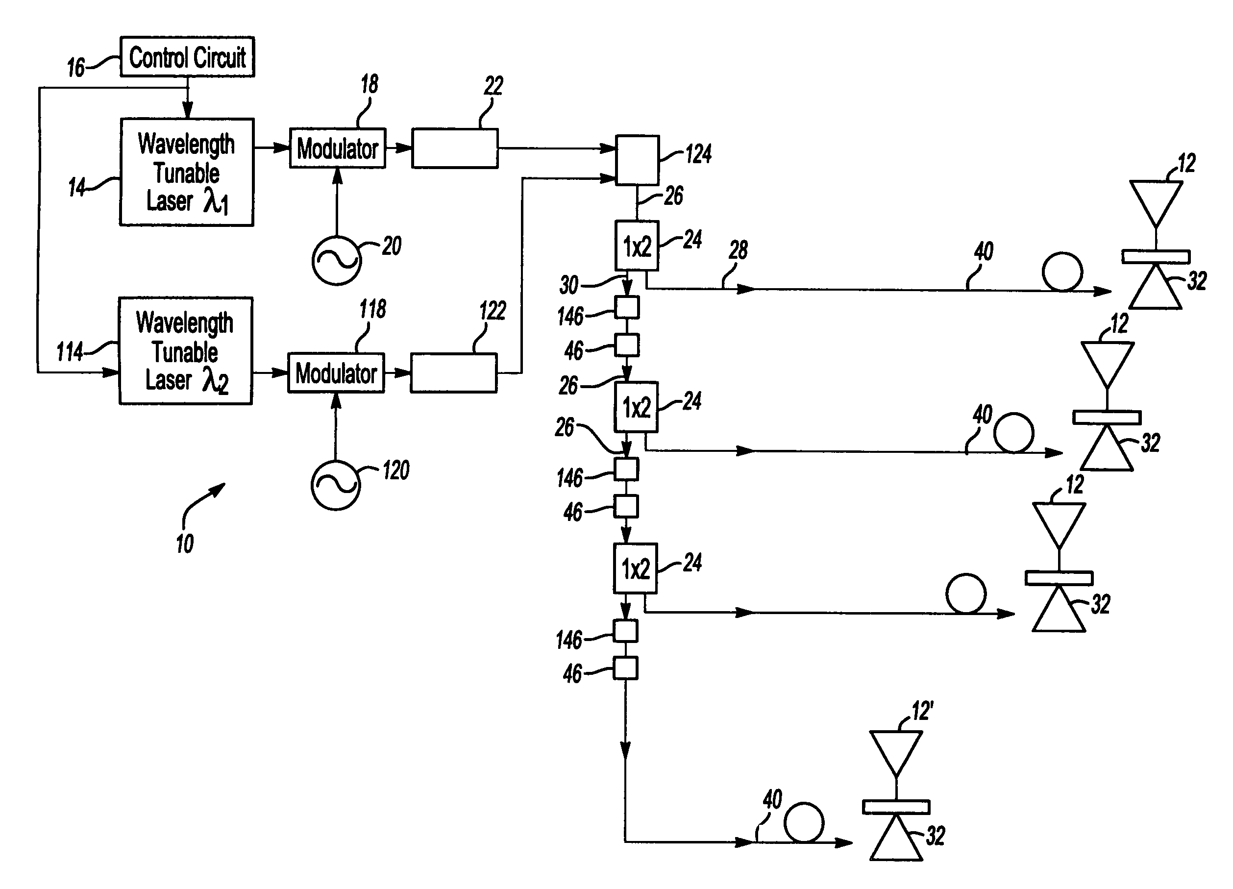
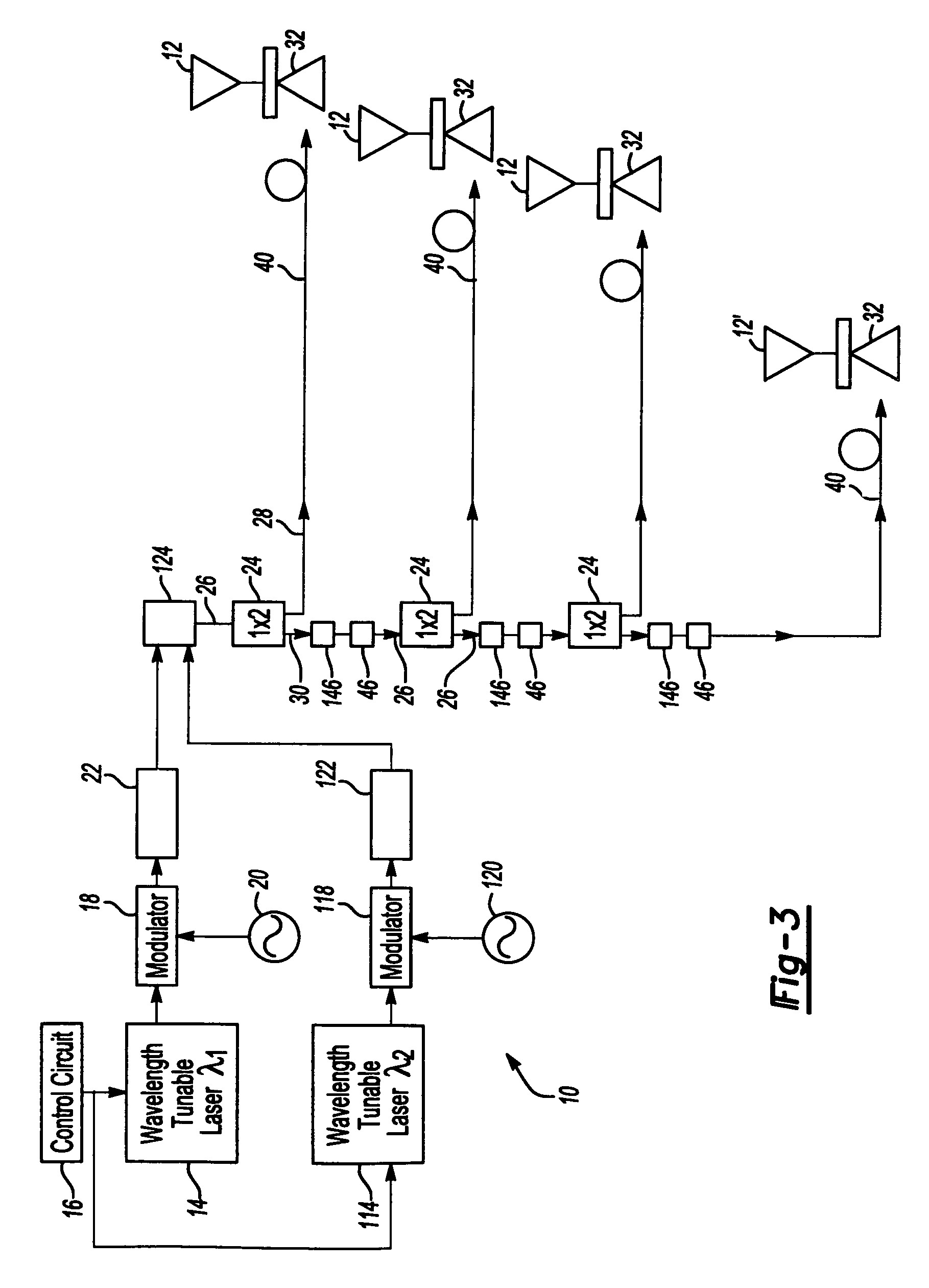
[0029]With reference now to FIG. 1, a block diagrammatic schematic view of the electro optical scanning antenna of the present invention is illustrated. The scanning antenna includes a wavelength tunable laser 14, such as a diode laser. A control circuit 16 controls the operation of the laser 14 to continuously vary the wavelength of the laser 14 within a predetermined range with a center wavelength of λ1.

[0030]The laser 14 has its output optically couple...


PUM


Abstract

An multi-beam multifunction electro optical scanning antenna having a first variable wavelength tunable laser having an output wavelength variable within a first range and a second variable wavelength tunable laser having an output wavelength variable within a second range, different from the first range. The outputs from both lasers are modulated by independent microwave sources and the modulated outputs from both lasers are combined by an optical combiner into a combined output signal. An antenna array includes a plurality of radiators and a photodetector is associated with each radiator which converts the combined optical output from the lasers to microwave signals. Beam splitters divide the combined output signals to each of the antenna radiators while first and second wavelength-dependent time delay elements are optically connected in series between each sequential beam splitter. Each first time delay element is operable within the first wavelength range, while each second time delay element is operable within the second wavelength range. The antenna can generate two or more RF microwave beams simultaneously and independently scan/steer them.

Description

CROSS REFERENCE TO RELATED APPLICATION[0001]This application is a continuation-in-part of U.S. patent application Ser. No. 11 / 005,623 filed Dec. 6, 2004.GOVERNMENT INTEREST[0002]The invention described herein may be manufactured, used, and licensed by or for the United States Government.FIELD OF THE INVENTION[0003]The present invention relates generally to scanning antennas and, more particularly, to a high frequency, multiple function electro optical scanning antenna.BACKGROUND OF THE INVENTION[0004]High frequency communication systems as well as radar systems typically use a phased antenna array to control the direction of the electromagnetic transmission. Phased array antennas are inherently narrow band antennas in which the scan angle varies as a function of the true time delay between the microwave radiation from each adjacent antenna element.[0005]In order to control the beam direction of the transmission, the previously known scanning antennas have utilized feed networks that...

Claims


Application Information

Patent Timeline
IPC IPC(8): H04B10/00H01Q3/22
CPCH01Q25/00H01Q3/2676
Inventor ZHOU, WEIMIN
Owner UNITED STATES OF AMERICA THE AS REPRESENTED BY THE SEC OF THE ARMY
Why Eureka
Try Eureka