Method and apparatus for controlling topographical variation on a milled cross-section of a structure

a technology of topographical variation and cross-section, which is applied in the field of topographical variation control on a cross-section of a structure, can solve the problems of less accurate cross-section measurement by automated metrology software, less accurate width determination, and difficult edge recognition, so as to improve the accuracy of metrology applications, reduce topographical variation on a cross-section, and improve the control of topographical variation.

Active Publication Date: 2009-11-03
FEI CO
View PDF10 Cites 11 Cited by
  • Summary
  • Abstract
  • Description
  • Claims
  • Application Information

AI Technical Summary

Benefits of technology

[0021]It is an object of the invention, therefore, is to allow improved control over topographical variations when milling a cross-section of a structure, such as reducing topographical variation on a cross-section of a write-head in order to improve the accuracy of metrology applications. A preferred embodiment of the invention described and claimed herein comprises the use of a protective layer deposited over the structure, followed by ion milling to expose the cross-section of the structure, and SEM metrology to determine dimensions such as the width of the structure. In a preferred embodiment of the invention, topographical variation is reduced by using a protective layer which comprises a material having mill rates at higher incidence angles (up to 90 degrees) that closely approximates the mill rates of the structure at those higher incidence angles. In another preferred embodiment of the invention, a protective layer of carbon is deposited over a structure composed of Permalloy to allow for improved metrology of the Permalloy structure. In still another preferred-embodiment of the invention, topographical variation can be intentionally introduced by using a protective layer that comprises a material having mill rates at higher incidence angles that do not closely approximate the mill rates of the structure at those higher incidence angles.

Problems solved by technology

Because FIB sputter-milling can cause significant damage to small structures, the structure surface is often coated with a protective layer of tungsten before milling begins.
Unfortunately, there are a number of problems when the above-described processes are used to monitor the width of very small structures such as modern write-head poles.
Curtaining can make edge recognition difficult and can possibly lead to a less accurate cross-section measurement by automated metrology software.
The resulting width determination is less accurate than if the vertical cross-section were to be measured directly.
Further, the process takes significant additional time because the cross-section must be milled, the sample rotated, and then the redeposited material must be removed before an SEM image can be taken and measurements can be performed.
Any increase in time required to complete a critical dimension measurement process is very undesirable for any in-line process control.

Method used


Image

  • Method and apparatus for controlling topographical variation on a milled cross-section of a structure
  • Method and apparatus for controlling topographical variation on a milled cross-section of a structure
  • Method and apparatus for controlling topographical variation on a milled cross-section of a structure

Examples


Embodiment Construction

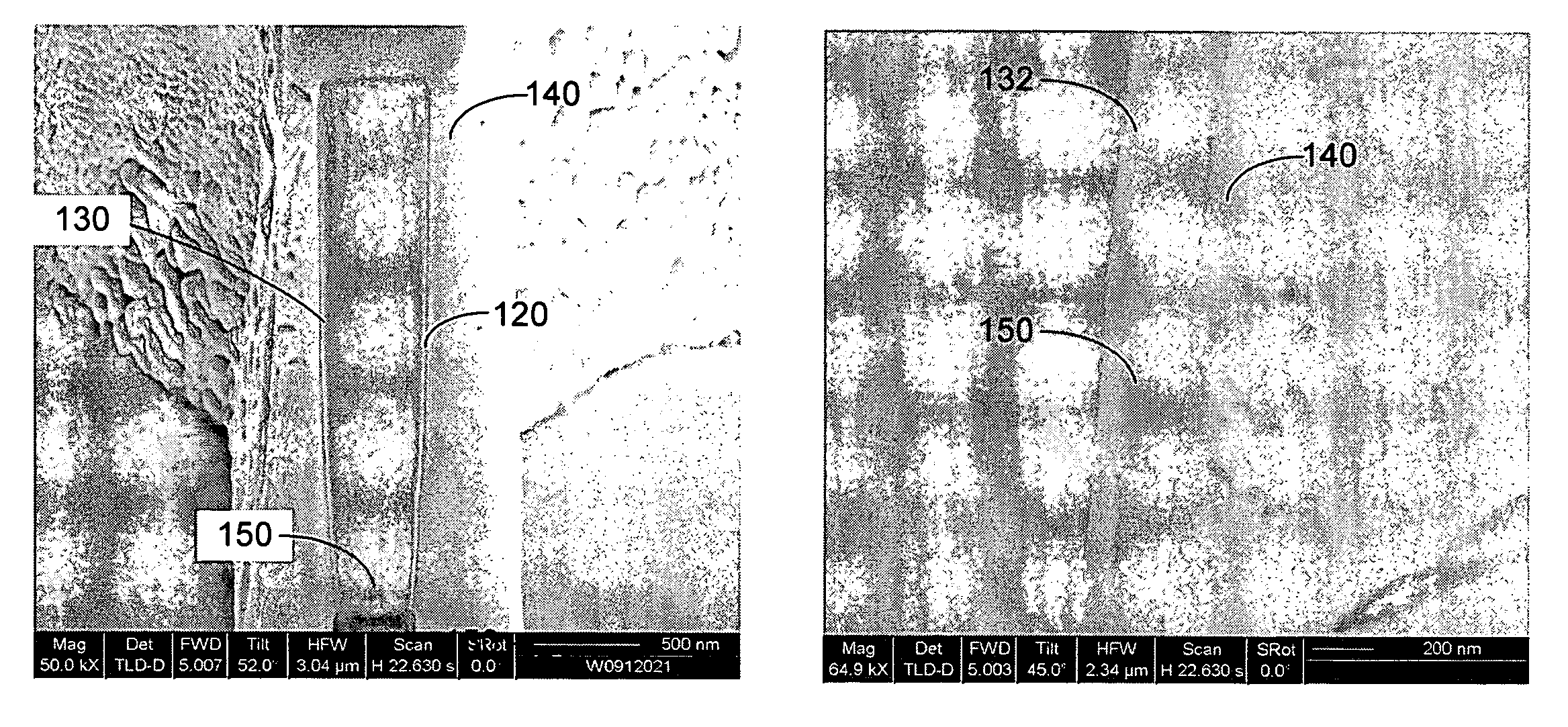
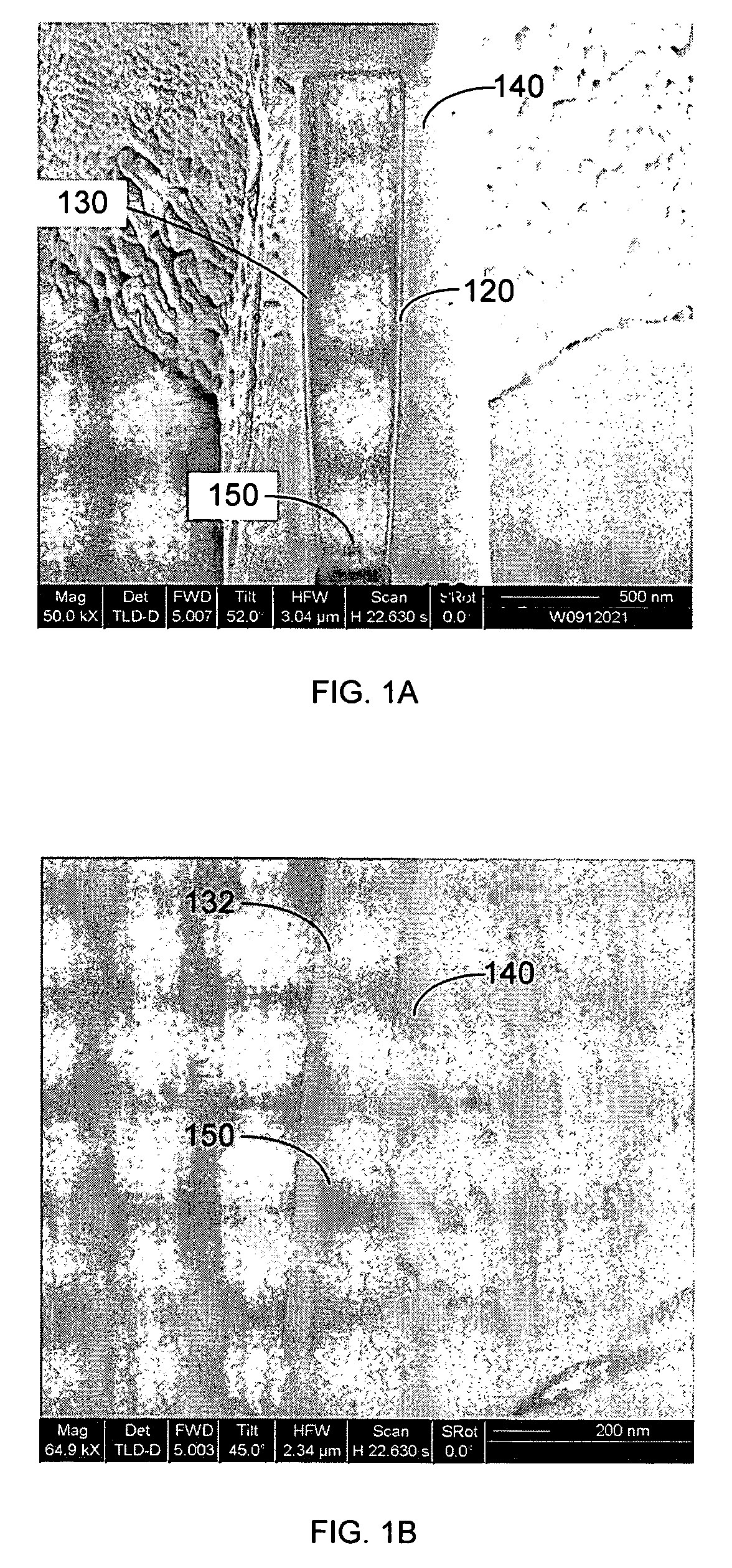
[0032]Preferred embodiments of the present invention are directed to methods and an apparatus for controlling topographic features or variations on a milled cross-section of a structure. The topographic features that can result from milling the cross-section can be reduced or even eliminated by careful matching of the substrate (the material that the feature is composed of) with a protective overcoat material. Specifically, an appropriate overcoat material according to the invention will have a mill rate at higher incidence angles (up to 90 degrees) that closely approximates the mill rate of the substrate material at those higher incidence angles at which the milling cross section is formed. Preferred embodiments of the present invention can thus be used to produce a cross-section face that is almost perfectly planar. This allows for SEM metrology based entirely upon material differences rather than variations in topography, which is desirable for metrology on a structure. In contra...


PUM

PropertyMeasurementUnit
incidence anglesaaaaaaaaaa
energyaaaaaaaaaa

Abstract

An improved method of controlling topographical variations when milling a cross-section of a structure, which can be used to reduce topographical variation on a cross-section of a write-head in order to improve the accuracy of metrology applications. Topographical variation is reduced by using a protective layer that comprises a material having mill rates at higher incidence angles that closely approximate the mill rates of the structure at those higher incidence angles. Topographical variation can be intentionally introduced by using a protective layer that comprises a material having mill rates at higher incidence angles that do not closely approximate the mill rates of the structure at those higher incidence angles.

Description

TECHNICAL FIELD OF THE INVENTION[0001]The present invention relates to charged particle beam milling and, in particular, to a method of controlling topographical variation on a cross-section of a structure.BACKGROUND AND SUMMARY OF THE INVENTION[0002]Semiconductor manufacturing, such as the fabrication of integrated circuits, typically entails the use of photolithography. A semiconductor substrate on which circuits are being formed, usually a silicon wafer, is coated with a material, such as a photoresist, that changes solubility when exposed to radiation. A lithography tool, such as a mask or reticle, positioned between the radiation source and the semiconductor substrate casts a shadow to control which areas of the substrate are exposed to the radiation. After the exposure, the photoresist is removed from either the exposed or the unexposed areas, leaving a patterned layer of photoresist on the wafer that protects parts of the wafer during a subsequent etching or diffusion process...

Claims


Application Information

Patent Timeline
Patent Type & Authority Patents(United States)
IPC IPC(8): C23C14/35C23F1/00G11B5/31
CPCG11B5/3163H01J2237/3114
Inventor NADEAU, JAMES P.ZOU, PEIARJAVAC, JASON H.
Owner FEI CO
Why Eureka
Try Eureka