Membrane suppressor with an outlet substantially non-retentive for ionic species

a suppressor and membrane technology, applied in the direction of ion-exchangers, separation processes, instruments, etc., can solve the problems of significant reduction of the conductivity of analytes, and the exhaustion of the suppressor chromatographic effluent channel

Active Publication Date: 2009-11-17
DIONEX CORP
View PDF18 Cites 19 Cited by
  • Summary
  • Abstract
  • Description
  • Claims
  • Application Information

AI Technical Summary

Problems solved by technology

During the operation of ion chromatographic system, it is possible that the suppressor chromatographic effluent channel becomes exhausted if the electrical current is inadvertently turned off due to operator errors or instrument malfunctions.
It is also possible that the suppressor chromatographic effluent channel become exhausted because the applied current to the suppressor is too low relative to the concentration of chromatographic eluent.
When the suppressor chromatographic effluent channel becomes exhausted, the ion exchange sites are converted to the form of eluent cations (e.g., sodium form if a suppressor is used to suppress sodium hydroxide), analyte ions (e.g., chloride ions) exit the suppressor in the less conductive salt form (i.e., NaCl) instead of the more conductive acid form (i.e., HCl), and the conductivity of the analytes may becomes significantly smaller, which has obviously detrimental effects in analytical determination of the target analytes using ion chromatography.
However, the prior-art electrolytic suppressors discussed above may not be fully regenerated rapidly upon application of electric field in the event that the chromatographic effluent channels become exhausted.
However, some ion exchange sites associated with outlet regions of the chromatographic effluent channels of the prior-art electrolytic suppressors may be located outside of the electromigration pathway of regenerant ions, and those ion exchange sites may not be electrolytically regenerated.
The presence of target analyte ions in two forms (H+X− and Na+X−) in varying ratio leads the varying conductivity response of the target analyte ions and is detrimental to accurate determination of the target analyte.
Thus, the slow recovery of electrolytic suppressor can hamper its performance in ion chromatography.

Method used


Image

  • Membrane suppressor with an outlet substantially non-retentive for ionic species
  • Membrane suppressor with an outlet substantially non-retentive for ionic species
  • Membrane suppressor with an outlet substantially non-retentive for ionic species

Examples


example 1

Preparation of Functionalized Polymeric-Based Ion Exchange Tubing or Membrane or Screen with Continuous Non-Functionalized Section

[0068]The polymeric-based cation exchange capillary tubing with continuous non-functionalized section is formed as follows. The base polymeric capillary tubing is made of a PTFE (Teflon) type supplied by Zeus Inc. (Orangeburg, S.C.). The length of the capillary tubing is typically 20 to 50 cm and its internal diameter is typically 0.001 inch to 0.010 inch with a typical wall thickness of 0.001 to 0.010 inch. A defined length of such tubing (e.g., 10 to 90% of the entire starting length of the tubing) is immersed in a solution of 30% styrene w / w in methylene chloride solvent. Grafting occurs by irradiation with gamma rays at a dose of 10,000 rads / hour for about 48-120 hours at 80-90° F. under nitrogen atmosphere. The grafted section of the PTFE tubing is then soaked in 10% w / w chlorosulfonic acid in methylene chloride for 4 hours at about 40° C. The grafte...

example 2

Preparation of Functionalized Polymeric-Based Ion Exchange Tubing or Membrane or Screen with Continuous Non-Functionalized Section Through Selective Decomposition of Ion Exchange Sites

[0071]This example describes the method to prepare the polymeric-based cation exchange capillary tubing with continuous non-functionalized section through selective decomposition of ion exchange sites on a defined section of a continuous piece of ion exchange material such as tubing, membrane or screen. The preparation of cation exchange membrane with continuous non-functionalized section is given as an example.

[0072]A piece of fully sulfonated ion exchange membrane was prepared using a PTFE film as the starting material as described in Example 1. A defined section of this piece of sulfonated membrane was then immersed in a reaction vessel containing a solution of 6% sodium hypochlorite while the remaining section of the membrane was not in contact with the sodium hypochlorite solution. The reaction ve...

example 3

Separation of Common Anions Using Capillary Ion Chromatography System Employing a Capillary Electrolytic Suppressor with Non-Functionalized Outlet Section

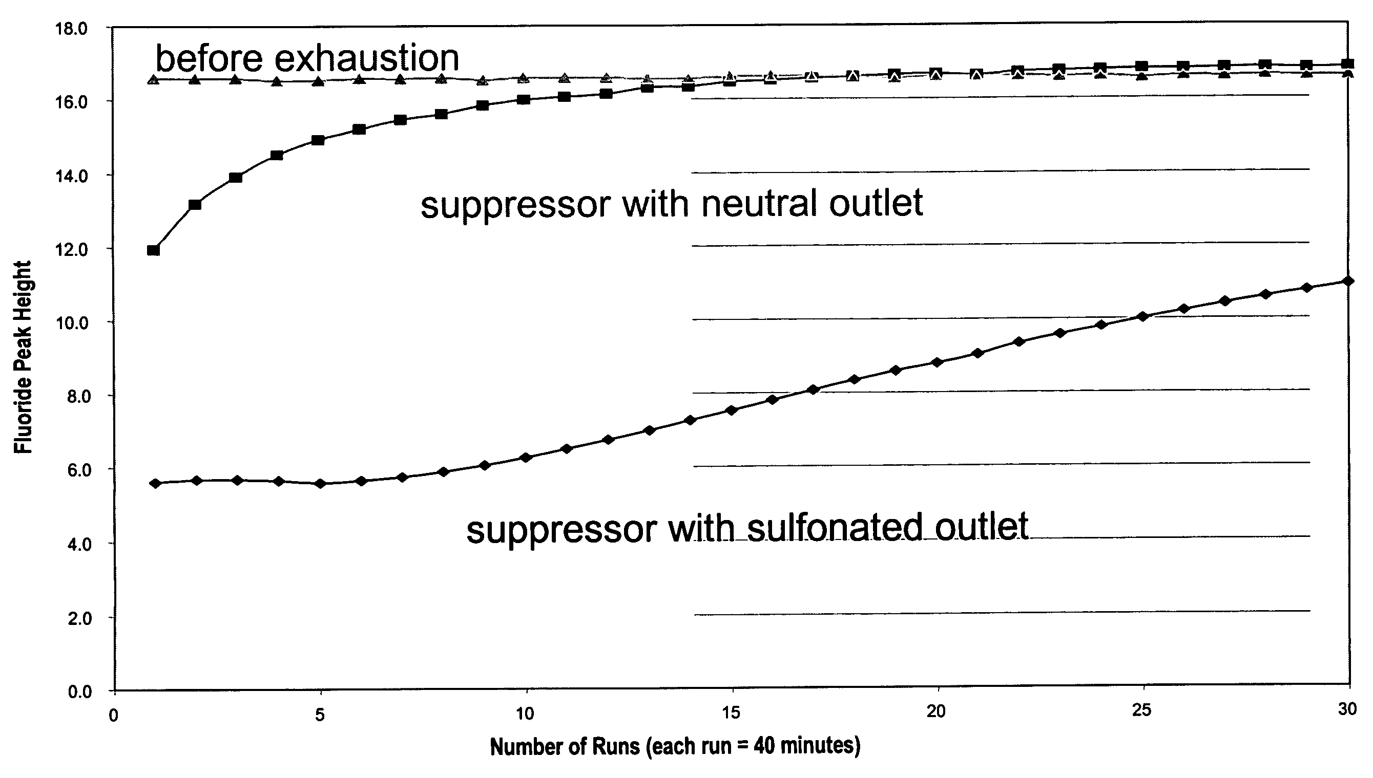
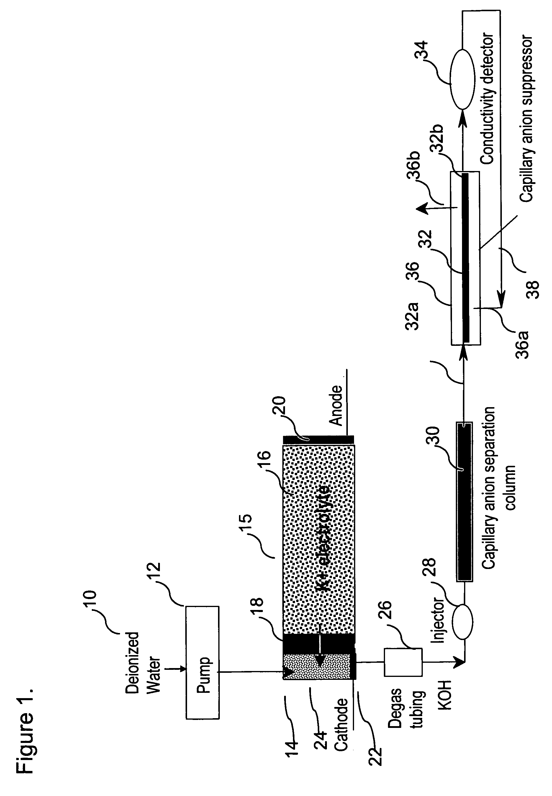
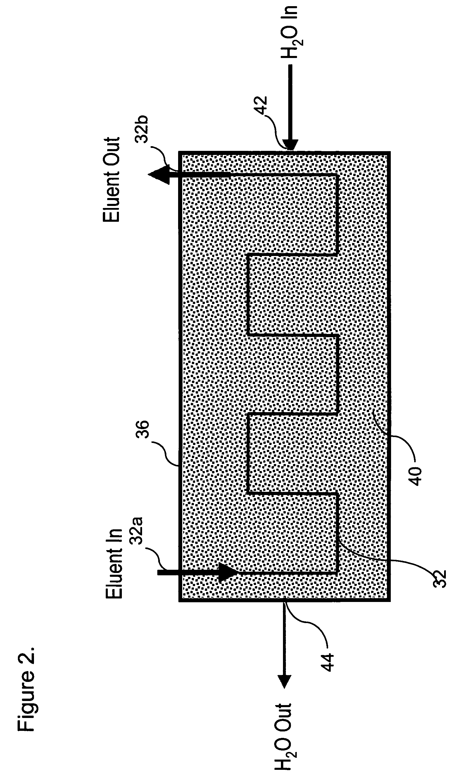
[0074]This example demonstrates the use of electrolytic capillary anion suppressors of the type depicted in FIG. 4 in the capillary IC separation of common anions. The capillary IC system used in the experiment was constructed according to the scheme shown in FIG. 1. A modified Dionex P680 pump (Dionex Corporation, Sunnyvale, Calif.) was used to deliver deionized water at 12 μL / min. To generate a KOH eluent, deionized water was first passed through Dionex ATC-HC and CTC-1 columns to remove ionic contaminants and then routed into a KOH eluent generator that was prepared by modifying a Dionex EGC-KOH cartridge (P / N 058900). A Keithley Model 220 Programmable Current Source (Keithely Instruments, Inc., Cleveland, Ohio) was used to supply the DC current to the anode and cathode of the KOH eluent generator. The outlet of the KOH eluent g...


PUM

PropertyMeasurementUnit
bore diameteraaaaaaaaaa
capillary flow ratesaaaaaaaaaa

Abstract

An apparatus for ion chromatography comprising a suppressor comprising a housing and a liquid conduit segment disposed in the housing, the liquid conduit segment including a membrane, the membrane having an inlet section adjacent the inlet of the conduit segment and an outlet section adjacent the outlet of the conduit segment, the inlet section having ion exchange sites capable of transmitting ions of one charge, positive or negative, and the outlet section being substantially non-retentive electrostatically for charged ionic species. Also, the method of using the apparatus.

Description

BACKGROUND OF THE INVENTION[0001]Ion chromatography has become a widely used analytical technique for the determination of anionic and cationic analytes in various sample matrices since it was introduced in 1975. Even though ion chromatography today comprises a number of separation and detection modes, ion chromatography with suppressed conductivity detection remains the most widely practiced form of the technique. In suppressed conductivity detection, an eluent suppression device, or suppressor, is the critical system component used to suppress the eluent, i.e., convert the eluent into a weakly conducting form and enhance the conductance of target analytes. The original suppressors were simply columns packed with ion-exchange resins in appropriate ionic forms. Those packed-bed suppressors required frequent off-line chemical regeneration. To overcome this problem, suppressors based on ion-exchange fibers and membranes were developed. These suppressors can be continuously regenerated...

Claims


Application Information

Patent Timeline
Patent Type & Authority Patents(United States)
IPC IPC(8): G01N30/02G01N33/00
CPCG01N30/96G01N2030/965
Inventor LIU, YANBARRETO, VICTORPOHL, CHRISTOPHER A.
Owner DIONEX CORP
Why Eureka
Try Eureka