Laser apparatus and manufacturing method of a battery

a laser apparatus and battery technology, applied in the field of laser apparatus and battery manufacturing method, can solve the problems of lithium battery, lithium battery, lithium battery, etc., and achieve the effect of reducing welding speed suppressing power fluctuation of pulsed laser light, and stabilizing penetration amoun

Inactive Publication Date: 2010-01-12
PANASONIC CORP
View PDF3 Cites 11 Cited by
  • Summary
  • Abstract
  • Description
  • Claims
  • Application Information

AI Technical Summary

Benefits of technology

[0018]The present invention is made in consideration with the disadvantages described above, and an object of the invention is to provide a laser apparatus capable of achieving deep penetration into an aluminum-like metal material without causing welding defects such as spatters and cracks as well as high-speed pulse seam welding, and a manufacturing method of a battery using the laser apparatus.
[0023]According to a preferred embodiment of the present invention, since a current signal whose fluctuation component is masked is supplied to the first laser oscillator, even when a high-speed (high-speed rise, short pulse width), high-peak pulsed laser light is oscillated by the first laser oscillator, power fluctuation of the pulsed laser light can be suppressed. Therefore, a reduction in the welding speed and stabilization of the penetration amount can be achieved. In addition, by oscillating a high-speed, high-peak pulsed laser light from the first laser oscillator, a penetration amount can be stabilized even when surface conditions of an aluminum-like metal material that is the processing object fluctuate.
[0024]Furthermore, by arranging a focus spot of CW laser light (continuous wave laser light) to take a rhombic streamlined shape, even when performing pulse seam welding on an aluminum-like metal material, a processing point can be preheated efficiently without having to increase the power of the CW laser light. Consequently, spatterless welding can be achieved. Moreover, since a focus spot of pulsed laser light is internally included in a focus spot of CW laser light, penetration of minute keyholes occurs instantaneously. In addition, since slow cooling of a processing point is performed by the CW laser light after welding, rapid heat change can be suppressed to prevent cracks from occurring.
[0025]Consequently, deep penetration into aluminum-like metal material can be achieved without causing welding defects such as spatters or cracks and, at the same time, high-speed pulse seam welding can be achieved. In addition, a penetration amount can be stabilized and a desired penetration amount can be satisfied. Therefore, it is now possible to achieve pulse seam welding of thick aluminum-like metal material such as the sealing of an aluminum-like metal container used in a lithium battery for a hybrid vehicle.
[0026]Furthermore, by oscillating a high-speed, high-peak pulsed laser light from the first laser oscillator, the energy per pulse can be kept low. Therefore, a GI optical fiber can now be used because only fine powdery spatters in the order of several ten μ which resemble smoke occur from an edge surface of a laser exit aperture even when using the GI optical fiber. Consequently, by using a GI optical fiber, a larger aperture can be used as compared to an SI optical fiber and power transmissibility to a processing point can be improved,

Problems solved by technology

However, while usable for sealing a lithium battery for a mobile device, the three-level waveform YAG pulsed laser light cannot be used for sealing a lithium battery for a hybrid vehicle.
However, while the superimposed laser light in which the circular-shaped pulsed laser light is superimposed with the linear-shaped CW laser light achieves spatterless welding that satisfies a desired penetration amount when sealing an NiH battery for a hybrid vehicle which uses a steel-like metal container, the superimposed laser light is unable to satisfy a desired penetration amount when sealing a lithium battery for a hybrid car which uses an aluminum-like metal container because heat escapes to the surroundings from a tip of a linear-shaped CW component.
In addition, increasing the CW component in order to attain a preheating effect causes deformation of the container and subsequently widens a gap between a wall surface of an opening of the container and the sealing member, which in turn creates a disadvantage that laser light leaks to an inner electrode and damages the inner electrode.
As seen, the conventional laser welding technique is not capable of performing pulse seam welding of thick aluminum-like metal material such as the sealing of an aluminum-like metal container used in a lithium battery for a hybrid vehicle.
Firstly, with aluminum-like metal material, since laser absorption factor varies significantly due to minute differences in surface conditions such as scratches, coarseness and staining, the penetration amount also varies significantly due to surface conditions.
On the other hand, during the sealing of an aluminum-like metal container, when laser light penetrates the sealing member, a spatter occurs from the penetrated portion and, in turn, causes a short circuit.
However, with a dropper power source, raising a current signal in the order of several hundred amperes at high speed significantly increases equipment size.
Therefore, the dropper power source is unsuitable for a laser apparatus to be used to weld aluminum-like metal material.
As a result, since reducing the pulse width of a current signal to be supplied to the excitation light source increases the proportion of a jitter component (fluctuation component) and causes a significant power fluctuation in the pulsed laser light, a stable penetration amount cannot be achieved.
Therefore, with a general dropper power source or a chopper / inverter power source, pulse reduction of a current signal to be supplied to an excitation light source could not be achieved.
However, an SI optical fiber is prone to damages due to on-site adherence of dust and the like during fiber exchange.

Method used


Image

  • Laser apparatus and manufacturing method of a battery
  • Laser apparatus and manufacturing method of a battery
  • Laser apparatus and manufacturing method of a battery

Examples


Embodiment Construction

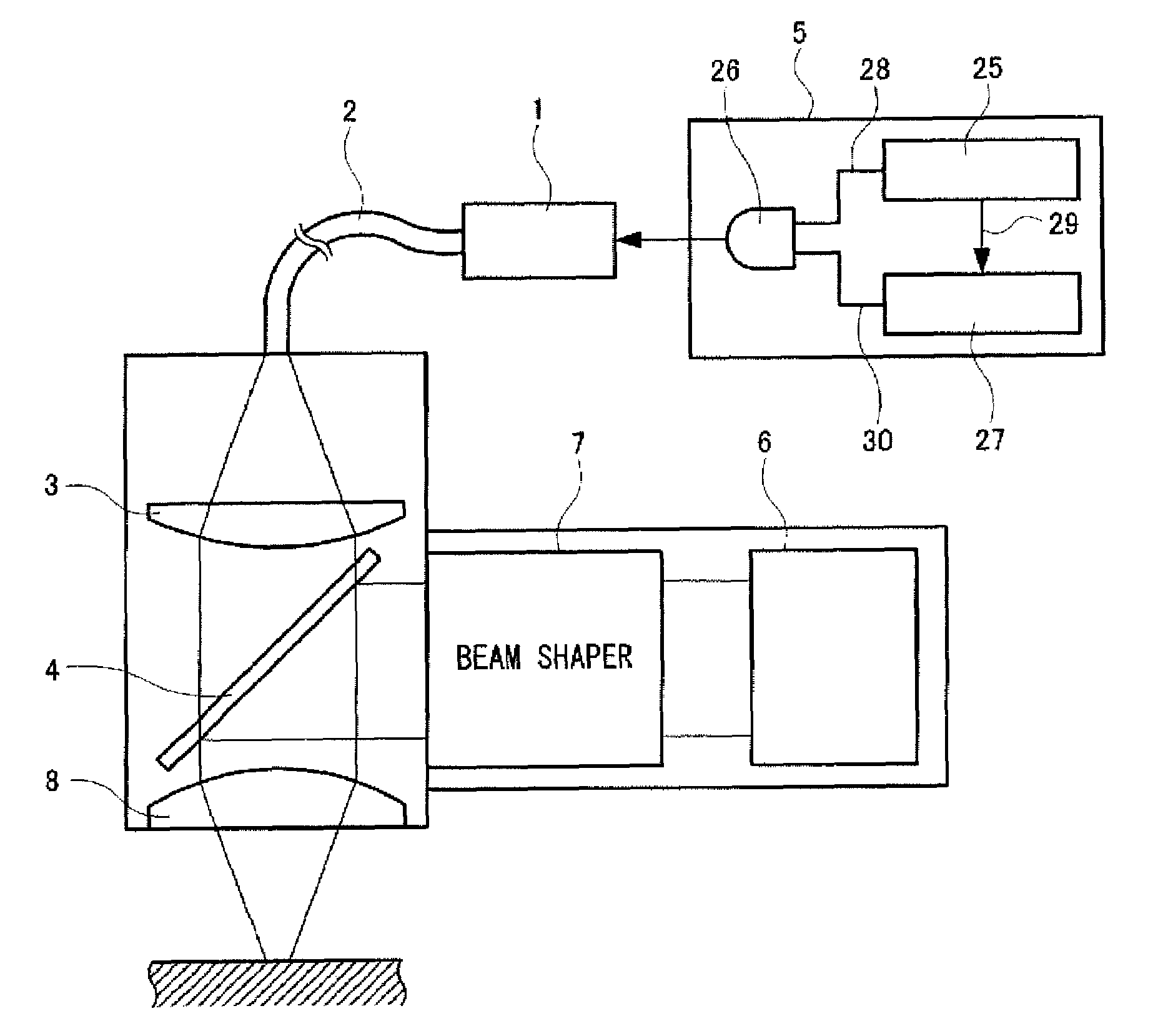
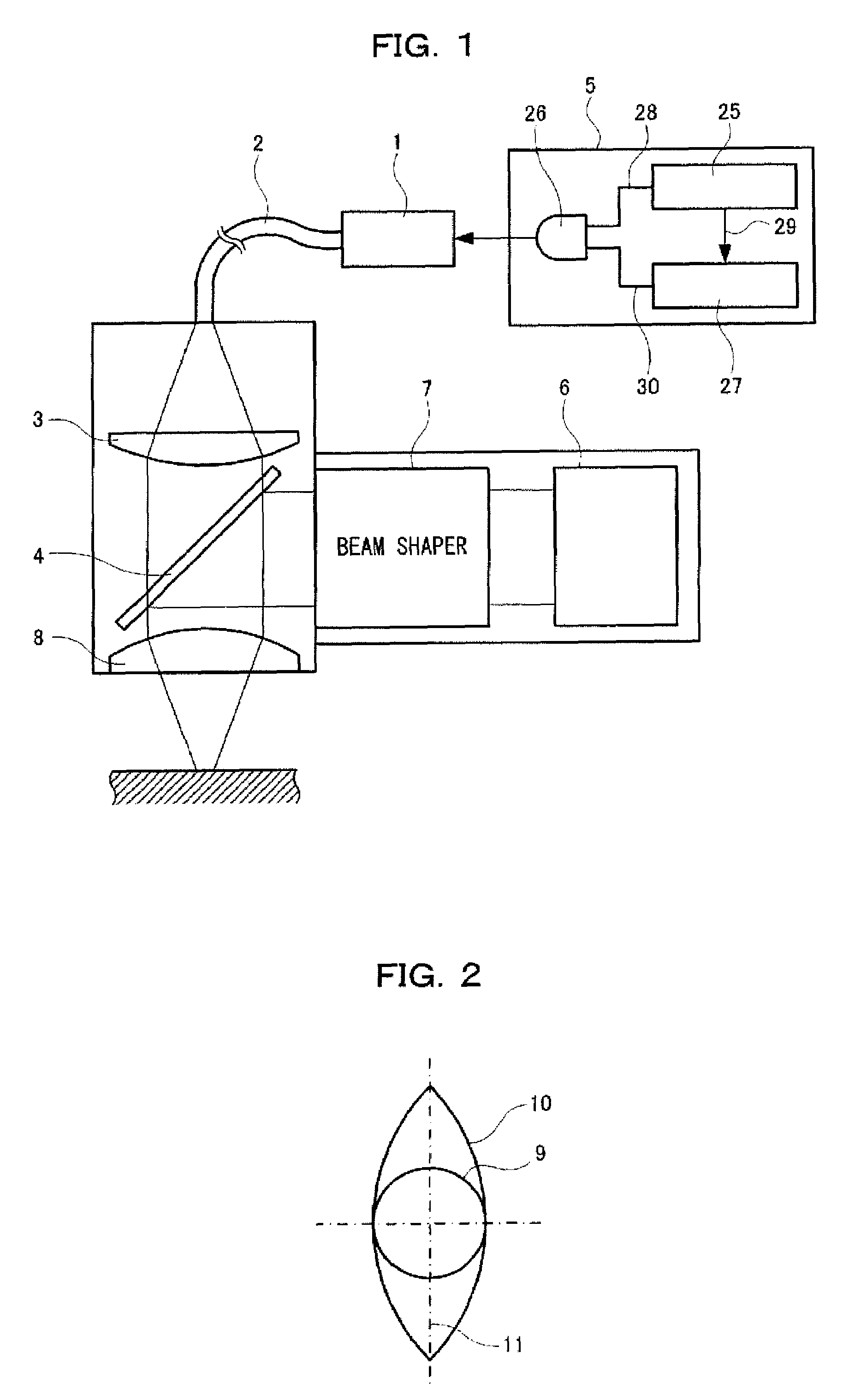
[0036]An embodiment of the present invention will now be described with reference to the drawings. FIG. 1 is a schematic diagram showing an example of a general configuration of a laser apparatus according to an embodiment of the present invention. The laser apparatus includes a YAG pulsed laser oscillator (first laser oscillator) 1 that oscillates a pulsed laser light with a wavelength of 1064 nm. A pulsed laser light oscillated by the oscillator 1 passes through a GI optical fiber 2 with a core diameter of 0.8 mm and is incident to a collimator lens 3. Subsequently, the pulsed laser light collimated by the collimator lens 3 is incident to a dichroic mirror 4.

[0037]In addition, although not shown, a YAG rod and an excitation light source are installed into the YAG pulsed laser oscillator 1. A pulse power source 5 for the excitation light source generates a current signal for causing the YAG pulsed laser oscillator 1 to oscillate a pulsed laser light of a desired pulse width and a p...


PUM

PropertyMeasurementUnit
rise timeaaaaaaaaaa
rise timeaaaaaaaaaa
oscillation wavelengthaaaaaaaaaa

Abstract

A laser apparatus is provided which is capable of achieving deep penetration into an aluminum-like metal material without causing welding defects such as spatters or cracks and performing high-speed pulse seam welding. The laser apparatus includes a pulse power source that generates a current signal and a mask signal for masking a fluctuation component included in the current signal, and which supplies a current signal in which a fluctuation component has been masked by the mask signal to a YAG pulsed laser oscillator. In addition, the laser apparatus sets the spot shape of a CW laser light oscillated by a CW laser oscillator to a rhombic streamlined shape, and causes a focus spot of the CW laser light to include a circular focus spot of a pulsed laser light.

Description

FIELD OF THE INVENTION[0001]The present invention relates to a laser apparatus that focuses a superimposed laser light in which a pulsed laser light is superimposed with a continuous wave laser light (CW laser light) at a processing point, and a method of manufacturing a battery using the laser apparatus.BACKGROUND OF THE INVENTION[0002]Conventionally, sealing of an aluminum-like metal container used in a lithium battery for a mobile device has been performed by pulse seam welding in which a YAG pulsed laser light is irradiated along a junction line between an opening of the container and a sealing member fitted into the opening. More specifically, when sealing an aluminum-like metal container, a YAG pulsed laser light is irradiated to each processing point in a three-level waveform. That is, first, cutting is performed with a high-speed, high-peak pulsed laser, and when the aluminum-like metal material starts to melt, laser power is immediately suppressed to around half to perform ...

Claims


Application Information

Patent Timeline
Patent Type & Authority Patents(United States)
IPC IPC(8): H01S3/10H01M50/183
CPCB23K26/0613B23K26/063B23K26/0736B23K26/206H01M2/08Y10T29/4911H01M10/052H01M2010/0495Y02T10/7011B23K26/0622Y02E60/10H01M50/183
Inventor SAKURAI, TSUTOMUFUNAMI, KOJI
Owner PANASONIC CORP
Why Eureka
Try Eureka