Methods for the compensation of imaging technique in the processing of radiographic images
a radiographic image and imaging technique technology, applied in the field of imaging and analysis, can solve the problems of large dxa system, large bmd measurement errors, limited accuracy of dxa scans,
- Summary
- Abstract
- Description
- Claims
- Application Information
AI Technical Summary
Benefits of technology
Problems solved by technology
Method used
Image
Examples
example 1
In Vivo Reproducibility and in Vivo Diagnostic Sensitivity
[0283]A. Dental X-Rays
[0284]In order to test in vivo reproducibility of data obtained from dental x-rays, the following experiment was performed. Subjects sat in a dental chair and an x-ray was taken of the area of the incisor teeth and of the molar teeth of the mandible. A calibration phantom step wedge was attached to the dental x-ray film. The dental x-ray film was exposed using standard x-ray imaging techniques for x-rays of the incisor area. The subjects walked around for 15 minutes at which point that test was repeated using the same procedure.
[0285]X-ray films were digitized on a commercial flat-bed scanner with transparency option (Acer ScanPremio ST). The regions of interest (ROIs) were placed manually at the same position with respect to the dental roots in all digitized x-rays of the same subject using the NIH Image software program (http: / / rsb.info.nih.gov / nih-image / Default.html). The reproducibility of the measur...
example 2
Image Processing Techniques
[0309]Techniques to analyze structure of trabeculae in different regions of the femoral head, neck, and proximal shaft are developed in Matlab (The MathWorks, Inc., Natick, Mass.) on PC's. The following techniques (modules) are developed: algorithms for software analysis of density, length, thickness, and orientation of trabeculae in different regions of interest (ROI) in the radiograph and a technique for automated placement of these ROI.
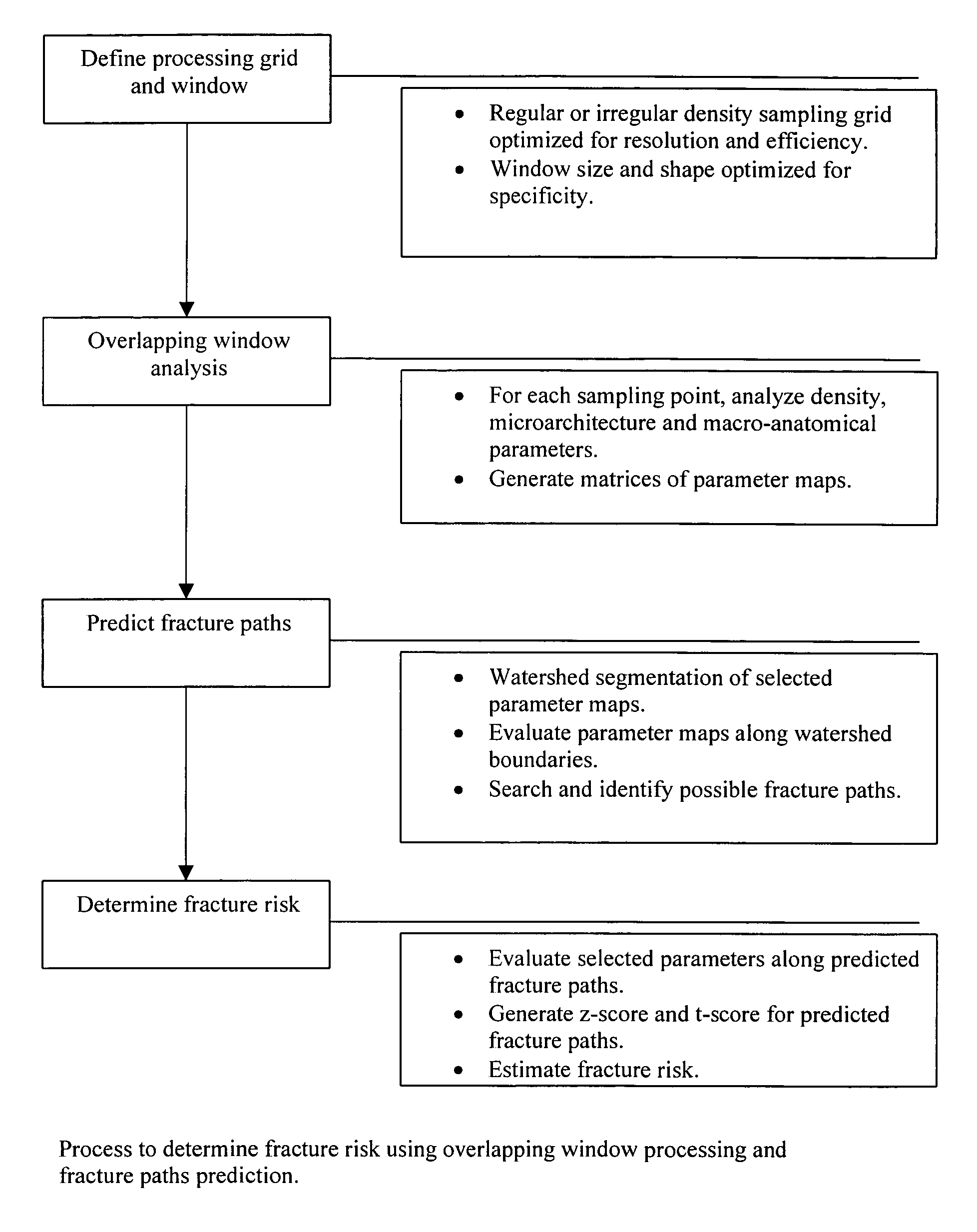
[0310]Six regions of interest are selected in the proximal femur for bone microstructure evaluation. The size and shape of these ROI are designed to capture the local changes of trabecular density and structure (see, e.g., FIG. 9), and may reflect the location of the different compressive and tensile groups of trabeculae. Singh et al. (1970) J Bone Joint Surg Am. 1970. 52:457-467. Thus, a classification scheme based on statistical convergence of multiple parameters that would provide a high precision index for predicting ...
example 3
Bone Structure Analysis of Hip Radiographs.
[0311]The trabeculae in the femur is extracted using the background subtraction method, essentially as described in Geraets et al. (1998) Bone 22:165-173. A copy of the image is blurred with a 15×15 Gaussian filter, and the result represents the non-uniform background. This background image is subtracted from the original image to obtain an image of trabecular structure. This image is then transformed into binary image of trabecular structure by applying a threshold value of 0. An example of the end result is shown in FIG. 10.
[0312]In a second step, parameters relevant to the geometry and connectivity of trabecular structure are measured on the trabecular skeleton or centerline. The skeletonization is performed using morphological hit-or-miss thinning for example as described in Soille, “Morphological image analysis: principles and application” Springer, 1998: p. 129-154. The branch points and end points of the skeleton network are detected...
PUM
 Abstract
Description
Claims
Application Information
 - R&D
- Intellectual Property
- Life Sciences
- Materials
- Tech Scout
- Unparalleled Data Quality
- Higher Quality Content
- 60% Fewer Hallucinations
Browse by: Latest US Patents, China's latest patents, Technical Efficacy Thesaurus, Application Domain, Technology Topic, Popular Technical Reports.
© 2025 PatSnap. All rights reserved.Legal|Privacy policy|Modern Slavery Act Transparency Statement|Sitemap|About US| Contact US: help@patsnap.com


