Method of manufacturing semiconductor device including gallium-nitride semiconductor structure and a palladium contact

a gallium-nitride and semiconductor technology, applied in semiconductor devices, lasers, semiconductor devices, etc., can solve the problems of difficult to achieve a low-resistance p-type semiconductor layer, and often considered insufficient as a layered structure for long-term stable operation. , to achieve the effect of long-term stable operation and no degradation of device performan

Active Publication Date: 2010-03-16
MITSUBISHI ELECTRIC CORP
View PDF7 Cites 0 Cited by
  • Summary
  • Abstract
  • Description
  • Claims
  • Application Information

AI Technical Summary

Benefits of technology

[0009]It is an object of the invention to provide a method of manufacturing a semiconductor device with a gallium-nitride-based semiconductor structure that allows long-term stable operation without degradation in device performance.
[0012]As a result, in forming a metal electrode by a combination of Pd and a high-melting-point metal, the high-melting-point metal can be selected from a diverse range of metals, which allows long-term stable operation of the semiconductor device.
[0013]Because the high-melting-point metal may be Ta, Cu, W, or the like, the semiconductor device can give long-term stable operation at current densities as high as or more than 20 kA / cm2.
[0014]Furthermore, the heat treatment in the step (e-2) will change a structure at the interface via the oxide between the contact layer and the metal, thus establishing a good ohmic contact. In other words, the presence of oxygen can promote the alloying of the contact layer with the metal electrode, thereby providing low contact resistance for ohmic contact.

Problems solved by technology

GaN-, AlGaN-, and InGaN-based semiconductor devices and other wide bandgap semiconductor devices have difficulty in achieving a low-resistance p-type semiconductor layer as compared to achieving an n-type semiconductor layer.
It is also difficult for a p-type semiconductor layer to provide low contact resistance for electrode contact with as compared with an n-type semiconductor layer.
Besides, a metal electrode layer formed on a p-type semiconductor layer is often considered insufficient as a layered structure for long-term stable operation.
This leads to a drawback that a layer-structure metal electrode layer cannot satisfactorily provide long-term stable operation.
Thus in an actual semiconductor laser element, a structure including an insulation film that is formed to provide a ridge structure for electrical and optical confinement has the problem that the insulation film may be removed, or reduced in thickness, during the process using a HF solution.
This will change electrical and optical confinement conditions in a semiconductor laser, thus giving an adverse effect on the laser properties.
In other words, there is a problem of degradation in the performance of a GaN-based semiconductor device.

Method used


Image

  • Method of manufacturing semiconductor device including gallium-nitride semiconductor structure and a palladium contact
  • Method of manufacturing semiconductor device including gallium-nitride semiconductor structure and a palladium contact
  • Method of manufacturing semiconductor device including gallium-nitride semiconductor structure and a palladium contact

Examples


first preferred embodiment

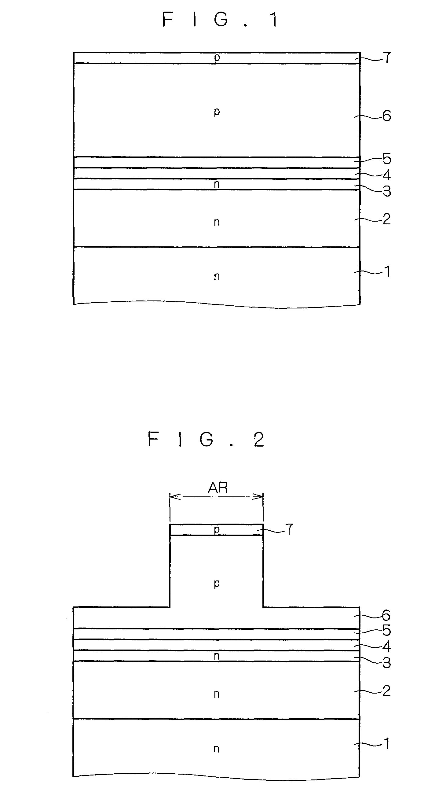
[0020]FIGS. 1 to 6 are cross-sectional views illustrating a method of manufacturing a GaN-based semiconductor device (semiconductor laser diode) according to a first preferred embodiment of the invention. Referring to these drawings, a manufacturing process in the method of manufacturing a semiconductor device according to the first preferred embodiment is described below.

[0021]First, as shown in FIG. 1, a layered structure (semiconductor structure) including an n-type AlGaN cladding layer 2, an n-type GaN guide layer 3, an InGaN quantum-well active layer 4, a GaN guide layer 5, a p-type AlGaN cladding layer 6, and a p-type GaN contact layer 7 is formed on an n-type low-resistance GaN substrate 1.

[0022]The n-type AlGaN cladding layer 2 is a layer for carrier and optical confinement, and the n-type GaN guide layer 3 is a layer for light propagation. The n-type GaN guide layer 3 may be replaced with an n-type InGaN guide layer.

[0023]The InGaN quantum-well active layer 4 is a light-emi...

second preferred embodiment

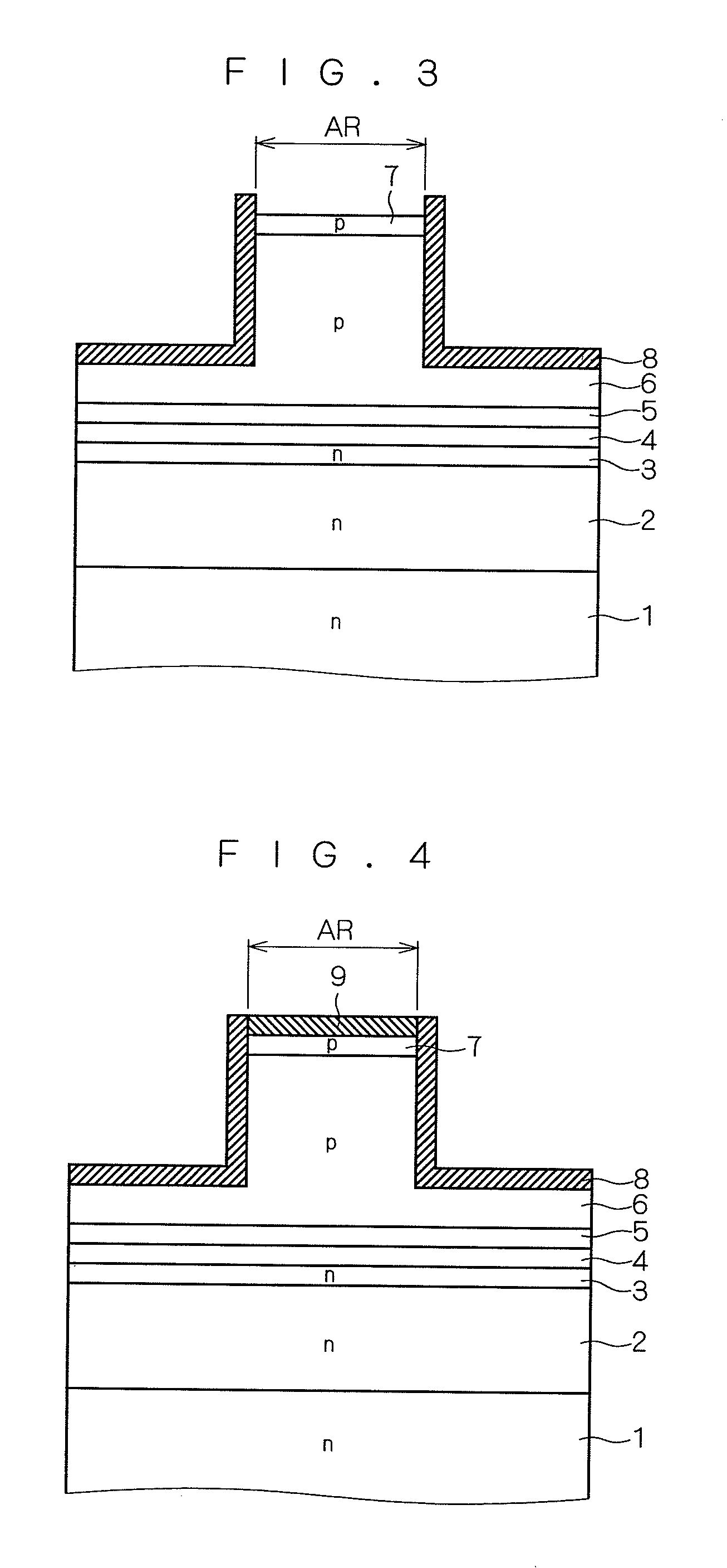
[0041]FIG. 7 is a cross-sectional view illustrating part of a method of manufacturing a GaN-based semiconductor device (semiconductor laser diode) according to a second preferred embodiment of the invention. Referring now to FIG. 7, a manufacturing process in the method of manufacturing a semiconductor device according to the second preferred embodiment is described.

[0042]After the steps of the first preferred embodiment in FIGS. 1 to 3, then as shown in FIG. 7, a metallic compound 19, which is also an oxide, is formed on the surface of the p-type GaN contact layer 7 by a deposition of a metallic compound that contains oxygen or both oxygen and nitrogen, such as GaO, RuO, PdO, GaON, RuON, or PdON.

[0043]Then, through the steps of the first preferred embodiment in FIGS. 5 and 6, the same processing as described in the first preferred embodiment is performed, completing the manufacture of a GaN-based semiconductor device according to the second preferred embodiment. It is noted herein ...

third preferred embodiment

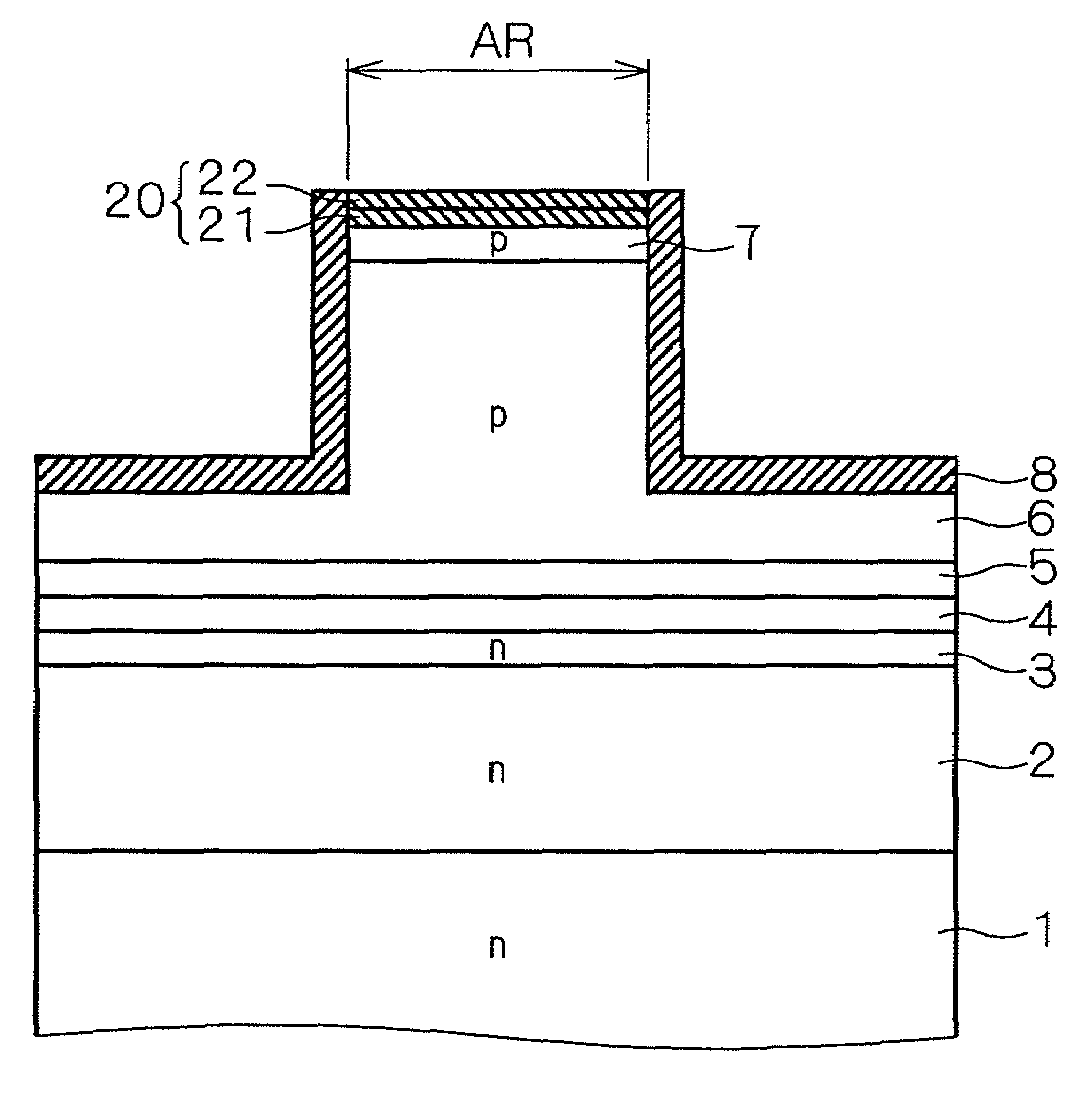
[0050]FIG. 8 is a cross-sectional view illustrating part of a method of manufacturing a GaN-based semiconductor device according to a third preferred embodiment of the invention. Referring now to FIG. 8, a manufacturing process in the method of manufacturing a semiconductor device according to the third preferred embodiment is described.

[0051]After the steps of the first preferred embodiment in FIGS. 1 to 3, then as shown in FIG. 8, an oxide film 21 is formed on the surface of the p-type GaN contact layer 7 by oxidation of the surface of the p-type GaN contact layer 7 with the supply of an oxygen-containing gas such as O2, O3, NO, N2O, or NO2.

[0052]Further, a metallic compound 22 is formed on the oxide film 21 by a deposition of a metallic compound that contains oxygen or both oxygen and nitrogen such as GaO, RuO, PdO, GaON, RuON, or PdON. These oxide film 21 and the metallic compound 22 form a layered oxide structure 20.

[0053]After that, through the steps of the first preferred emb...


PUM


Abstract

A method of manufacturing a semiconductor device provides a semiconductor device with a gallium-nitride-based semiconductor structure that allows long-term stable operation without degradation in device performance. After formation of an insulation film on a surface other than on a ridge surface, an oxygen-containing gas such as O2, O3, NO, N2O, or NO2 is supplied to oxidize a p-type GaN contact layer from the surface and to thereby form an oxide film on the surface of the p-type GaN contact layer. Then, a p-type electrode that establishes contact with the p-type GaN contact layer is formed by evaporation or sputtering on the oxide film and on the insulation film. Heat treatment is subsequently performed at temperatures between 400 and 700° C. in an atmosphere containing a nitrogen-containing gas such as N2 or NH3 or an inert gas such as Ar or He.

Description

BACKGROUND OF THE INVENTION[0001]1. Field of the Invention[0002]The present invention relates to a method of manufacturing a semiconductor device with a gallium-nitride-based semiconductor structure.[0003]2. Description of the Background Art[0004]GaN-, AlGaN-, and InGaN-based semiconductor devices and other wide bandgap semiconductor devices have difficulty in achieving a low-resistance p-type semiconductor layer as compared to achieving an n-type semiconductor layer. It is also difficult for a p-type semiconductor layer to provide low contact resistance for electrode contact with as compared with an n-type semiconductor layer.[0005]Besides, a metal electrode layer formed on a p-type semiconductor layer is often considered insufficient as a layered structure for long-term stable operation. For this reason, Japanese Patent Application Laid-open No. 10-209493, for example, discloses a lamination technique that provides good ohmic properties through the use of palladium (Pd) as a metal...

Claims


Application Information

Patent Timeline
Patent Type & Authority Patents(United States)
IPC IPC(8): H01L21/00H01L21/28H01L21/3205H01S5/042H01S5/22H01S5/323
CPCB82Y20/00H01S5/0425H01S5/22H01S5/34333H01L33/325H01L33/40H01S5/0421H01S5/2214H01S5/3063H01S5/04252
Inventor OHTSUKA, KENICHITARUI, YOICHIROSUZUKI, YOSUKESHIOZAWA, KATSUOMIKANAMOTO, KYOZOOISHI, TOSHIYUKITOKUDA, YASUNORIOMORI, TATSUO
Owner MITSUBISHI ELECTRIC CORP
Why Eureka
Try Eureka