
Sheet material for radio wave absorber and radio wave absorber

a radio wave absorber and sheet material technology, applied in the field of sheet material for radio wave absorbers and radio wave absorbers, can solve the problems of cost of storage, corner ends being broken, bulky radio wave absorbers molded with resin foam in this way, etc., to facilitate storage, transportation and workability of field assembling, and improve the form-retaining property of radio wave absorbers. , the effect of moderate rigidity

Active Publication Date: 2010-04-13
TORAY IND INC
View PDF36 Cites 11 Cited by
  • Summary
  • Abstract
  • Description
  • Claims
  • Application Information

AI Technical Summary

Benefits of technology

The present invention provides a sheet material for a radio wave absorber that solves problems of conventional technologies. The sheet material is light weighted with excellent form-retaining property and workability for field assembly. The radio wave absorber formed from the sheet material has excellent radio wave absorbing capacity and is still light weighted. The sheet material has a paperboard structure with a corrugated medium and a planar liner that are layered over each other, and includes electrical-loss material. The sheet material can be easily stored, transported, and worked in the field. The radio wave absorber formed from the sheet material has a hollow section, and is light weighted but has appropriate rigidity from the corrugated medium. The sheet material is compact for storage and does not cause distortion after assembly. The technical effects of the present invention are that it provides a light weighted sheet material with excellent radio wave absorbing capacity and form-retaining property, and a novel radio wave absorber formed from the sheet material.

Problems solved by technology

However, the radio wave absorber molded with the resin foam in this way is bulky and, moreover, fragile with the corner ends being broken by vibrations during the transportation or if they are knocked against something.
And this increases the necessary storage space and hence the cost of storage, and a large volumetric capacity is required for the packing in order to prevent it from being broken during transportation, increasing transportation cost and thus increasing the overall cost.
However, this carbon black containing plate material should be about 5 to 20 mm thick, because if it is too thin, distortion or shape instability can occur in the radio wave absorber after assembly, due to lack of rigidity.
Howsoever, if the plate material is made thick, its weight also increases, deteriorating onsite workability, making it difficult to reduce transportation cost, increasing the need for carbon black, and various other such problems.
However, the radio wave absorber assembled from this plate material of the honeycomb structure body has a problem of deteriorating the intrinsic functions as a radio wave absorber, because transmission of high-frequency electromagnetic wave is facilitated due to a structure where the cell opening is served as the radio wave incident face when the cell apertures of the honeycomb structure are large.
As a result, the weight is increased and therefore such problems of increasing the weight in the aforementioned Japanese patent application Kokai publication No. 1999-87978 and Japanese patent application Kokai publication No. 2000-216584 can not be essentially resolved.
And though the plate material of the aforementioned honeycomb structure body has rigidity against load in the thickness direction, the mechanical strength against load in a direction orthogonal to the thickness direction may lack in some cases, and hence it can not necessarily be said to improve the assembly workability on site.
However, the manufacturing cost becoming extremely high can not be avoided, because plastic paperboards are manufactured through extrusion molding.
In addition, there is a problem with on site assembly workability, because assembly requires local heating and softening treatment.
Moreover, when carbon black is used as the radio wave absorbing material, radio wave loss tends to decrease as the frequency becomes higher.
Therefore, there is the drawback that a radio wave absorber designed for an EMC anechoic chamber utilizing 30 MHz to 1 GHz as the main frequency range does not provide a sufficient absorbing property in microwave or milliwave ranges equal or higher than the same.

Method used


Image

  • Sheet material for radio wave absorber and radio wave absorber
  • Sheet material for radio wave absorber and radio wave absorber
  • Sheet material for radio wave absorber and radio wave absorber

Examples


embodiments

Embodiment 1

[0119]Carbon fiber having sizing agent content rate of 0% and average fiber length of 12 mm, chopped glass fiber and aramid pulp are mixed in a ratio of 3 wt %, 77 wt % and 20 wt % respectively and submitted to the wet paper-making method to obtain an incombustible sheet A including an electrical-loss material of 0.25 mm in thick, 150 g / m2 in basis weight. On the other hand, chopped glass fiber and aramid pulp are mixed in a ratio of 80 wt % and 20 wt % respectively and submitted to the wet paper-making method to obtain an incombustible sheet A not including an electrical-loss material of 0.25 mm in thick, 150 g / m2 in basis weight, and thereafter, a sheet B where a moss green color is printed on one side of the sheet is obtained. Here, the non-combustibility designates to be flameproof 1 grade of JIS A 1322 test, combustibility test, or V-0 class in UL-94 thin material vertical combustion test.

[0120]Thus obtained sheet A is used for the liner on one side and the corrugat...

embodiment 2

[0125]A paperboard same as the one manufactured in the embodiment 1 is cut into four (4) sheet material of 60 cm×101 cm, short sides of two of them are joined respectively with a paper tape, to make two (2) wedge form assemblies of 30 cm×60 cm bottom side×1 m height. These two wedge form assemblies are fixed in a way to arrange on a sintered ferrite plate of 60 cm in length×60 cm in width×5.7 mm in thickness, and an aluminum plate of 60 cm in length×60 cm in width×1 mm in thickness is affixed to the back of the sintered ferrite plate, to obtain a wedge form radio wave absorber of 60 cm×60 cm bottom side×about 1 m height.

[0126]In the manufacturing process of the aforementioned radio wave absorber, no distortion or the like has occurred in the assembly, and it could be assembled as a radio wave absorber presenting an excellent form-retaining property. In addition, the radio wave-absorbing property of thus obtained radio wave absorber was measured, to obtain an excellent radio wave-abs...

embodiment 3

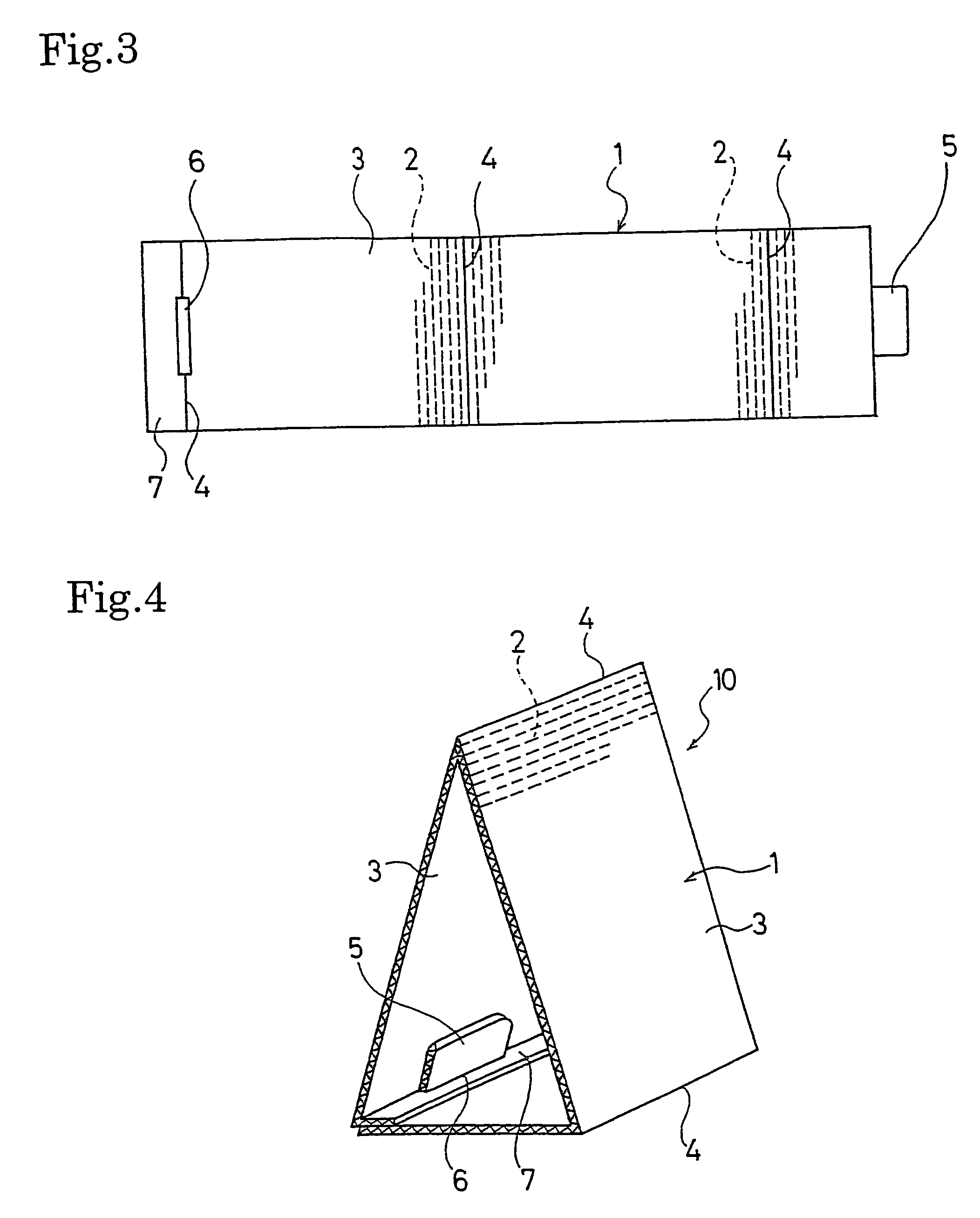
[0127]A paperboard same as the one manufactured in the embodiment 1 is cut to have embossed folds, insert flaps and insert slits as shown in FIG. 3 to work out two (2) sheet materials for assembly. Two (2) wedge form assemblies of 1 m height, 30 cm×60 cm bottom side respectively as shown in FIG. 4 were made from these two (2) sheet materials for assembly. These two wedge form assemblies are fixed in parallel on a sintered ferrite plate same as the embodiment 2, and an aluminum plate same as the embodiment 2 is affixed to the back of the sintered ferrite plate, to obtain a wedge form radio wave absorber of 60 cm×60 cm bottom side×about 1 m height.

[0128]In the manufacturing process of the aforementioned radio wave absorber, no distortion or the like has occurred in the assembly, and it could be assembled as a radio wave absorber presenting an excellent form-retaining property. In addition, the radio wave-absorbing property of thus obtained radio wave absorber was measured, to obtain a...


PUM

PropertyMeasurementUnit
thicknessaaaaaaaaaa
lengthaaaaaaaaaa
thickaaaaaaaaaa

Abstract

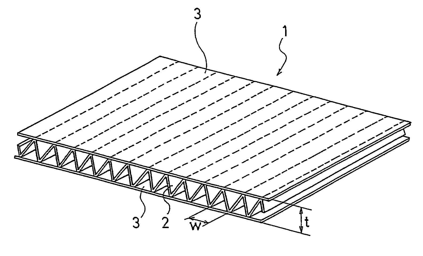
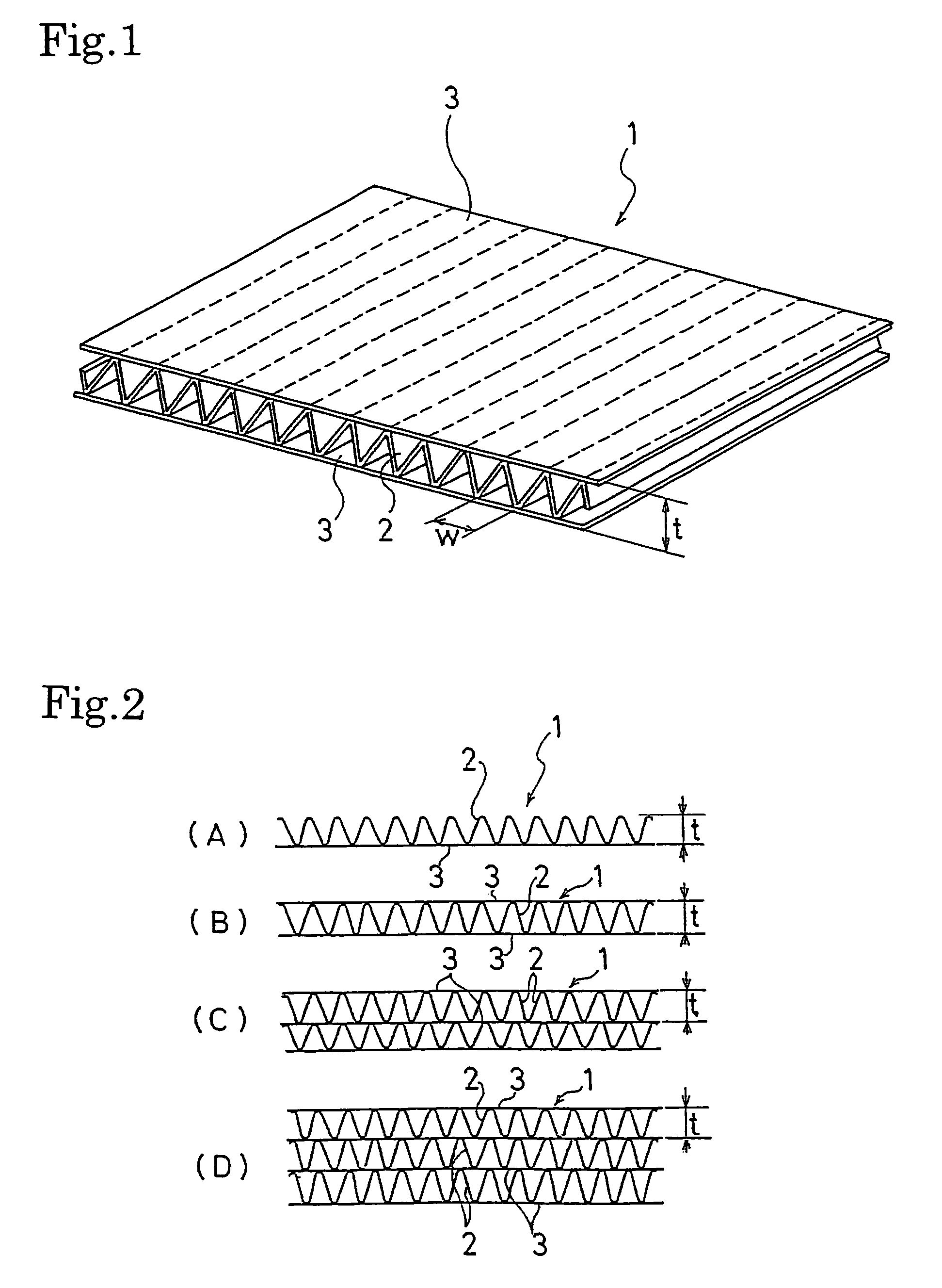
A sheet material for a radio wave absorber and a radio wave absorber formed from the sheet material, where the sheet material is light weighted and has excellent form-retaining capability and workability for field assembling. A sheet material (1) for a radio wave absorber has a corrugated paperboard structure with an undulated corrugated medium (2) and a planar liner (3) that are layered over each other. The corrugated medium (2) and / or the liner (3) are constructed from a sheet including an electrical-loss material. A radio wave absorber (10) is characterized in that the sheet material (1) for a radio wave absorber is cut, folded, and assembled as a hollow three-dimensional structure body, which has a shape of wedge, polygonal pyramid, or polygonal cylinder.

Description

[0001]This application is a 371 of international application PCT / JP2003 / 016452, which claims priority based on Japanese patent application Nos. 2002-374272 and 2003-183026 filed Dec. 25, 2002, and Jun. 26, 2003, respectively, which are incorporated herein by reference.TECHNICAL FIELD[0002]The present invention concerns a sheet material for a radio wave absorber and a radio wave absorber made of this sheet material for assembly and, more particularly, a sheet material for a radio wave absorber that can be used in the walls, ceiling and floor of an anechoic chamber and a radio wave absorber thereof.BACKGROUND ART[0003]The anechoic chamber is used for measurement testing the properties of antennae or radio-wave measurement testing an electronic device.[0004]A radio wave absorber is fitted to the walls, ceiling, floor and so on of the anechoic chamber used in such measurements so as to shield the inside from external radio wave and, at the same time, prevent any radio waves generated fr...

Claims


Application Information

Patent Timeline
Patent Type & Authority Patents(United States)
IPC IPC(8): B29D22/00B32B3/28B65D85/86H01Q17/00B32B29/08H05K9/00
CPCB32B29/08H01Q17/00H01Q17/004H05K9/0003Y10T428/1314Y10T428/24694Y10T428/1372Y10T428/1303B32B7/12B32B2307/212
Inventor KASABO, MIKIHATAKEYAMA, KENICHIFUJIMURA, YOICHI
Owner TORAY IND INC
Learn More