

High resistance magnet and motor using the same
a high-resistance magnet and motor technology, applied in the direction of magnetic bodies, magnetic circuits characterised by magnetic materials, instruments, etc., can solve the problems of thermal demagnetization properties, anisotropy, corrosion resistance, etc., and achieve the effect of improving the magnetic properties of rare earth element magnets
- Summary
- Abstract
- Description
- Claims
- Application Information
AI Technical Summary
Benefits of technology
Problems solved by technology
Method used
Image

Examples
embodiment 1
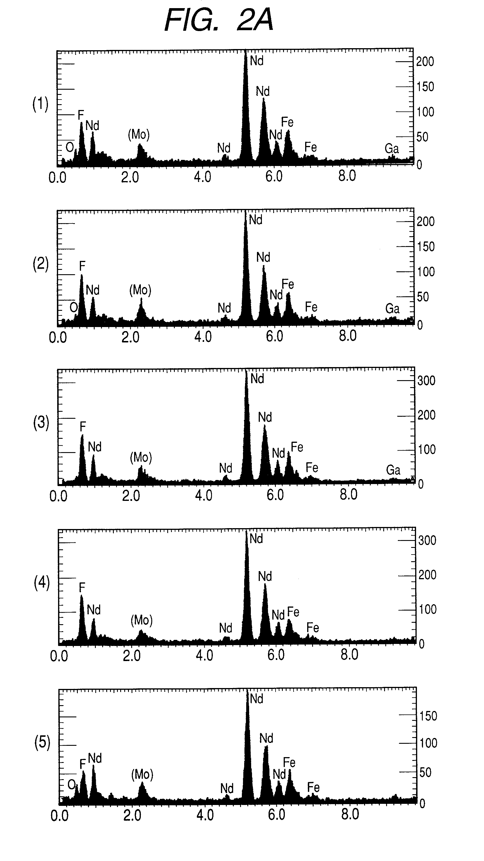
[0039]Quenched powder containing a main amount of Nd2Fe14B was prepared as NdFeB group powder. The quenched powder contained Nd2Fe14B as a main phase, Nd rich phase and B rich phase such as Nd1.1Fe4B4. In the examples of the specification, the NdFeB powder is the same material as mentioned above, otherwise specified. A fluorine compound was formed on the surface of the powder. When NdF3 is formed on the quenched powder, Nd(CH3COO)3 as a starting material was dissolved in water and HF was added thereto. When HF was added, gelatin of NdF3 xH2O was formed. The resulting product was centrifuged to remove the solvent. The product was admixed with NdFeB powder and was coated. The solvent of the mixed product was vaporized and heated to evaporate hydrolyzed water. The resulting film was subjected to analysis with XRD (energy diffraction X ray analysis).
[0040]The film was formed along the uneven surface of the NdFeB powder. As a result, it was revealed that the film comprised NdF3, NdF2, Nd...
embodiment 2
[0048]A DyF3 layer or TbF3 layer was formed on Nd2Fe14B magnetic powder with a high residual magnetic flux density to which an additive element with a high coercive force such as Dy, Tb or Pr is not added, thereby to achieve a high residual magnetic flux density and high coercive force. An alloy having a composition close to Nd2Fe14B was melted by a high frequency melting to produce a cast ingot. The ingot was crushed by a crusher to obtain powder having a particle size of 1 to 10 μm.
[0049]In order to form a fluorine compound layer on the powder, a treating solution, which was prepared by gelatin DyF3.×H2O or TbF3.×H2O was centrifuged to remove a solvent, was admixed with the above powder. The solvent of the mixture was evaporated and the mixture was heated to remove hydrated water.
[0050]The resulting powder was press-molded in a lateral magnetic field or a vertical magnetic field of 1T thereby to orient the magnetic powder. Thereafter, the powder was sintered in vacuum at a tempera...
embodiment 3
[0054]Quenched powder whose main component is Nd2(Fe, Co)14B as NdFeB group powder was prepared. A fluorine compound was formed on the surface of the quenched powder. The quenched powder may contain amorphous portions. In forming DyF3 on the surface of the quenched powder, a solution of Dy(CH3COO)3 was dissolved in water and HF was added to produce gelatin DyF3.×H2O. The resulting compound was subjected to centrifugation to remove a solvent. The resulting was admixed with NdFeB powder. The solvent of the mixture was vaporized and the mixture was heated to remove hydrated water.
[0055]The resulting fluorine compound layer having a thickness of 700 μm was investigated by an XRD. As a result, it was found that the fluorine compound film comprised DyF3, DtF2, DyOF, etc. The magnetic powder having a particle size of 1 to 300 μm was heated at a temperature lower than 800 do° C. at which the magnetic properties become worse, while preventing oxidation, to produce magnetic powder having a hi...
PUM
| Property | Measurement | Unit |
|---|---|---|
| particle size | aaaaa | aaaaa |
| particle size | aaaaa | aaaaa |
| average crystal grain size | aaaaa | aaaaa |
Abstract
Description
Claims
Application Information