Reciprocating piston machine

a reciprocating piston machine and piston technology, applied in mechanical equipment, pumps, engines without rotary main shafts, etc., can solve the problems of increasing the friction torque during screw-in operation, superimposing additional thermal stresses on these forces, and high peripheral stresses in the housing

Inactive Publication Date: 2010-04-20
LUK FAHRZEUG HYDRAULIK
View PDF4 Cites 2 Cited by
  • Summary
  • Abstract
  • Description
  • Claims
  • Application Information

AI Technical Summary

Benefits of technology

[0004]It is an object of the present invention to provide a compressor which will not have these disadvantages.

Problems solved by technology

This radial pressure on the housing leads to relatively high peripheral stresses in the housing and increases the friction torque during the screw-in operation.
Moreover, additional thermal stresses are superposed on these forces during operation and at standstill.

Method used


Image

  • Reciprocating piston machine
  • Reciprocating piston machine
  • Reciprocating piston machine

Examples


Embodiment Construction

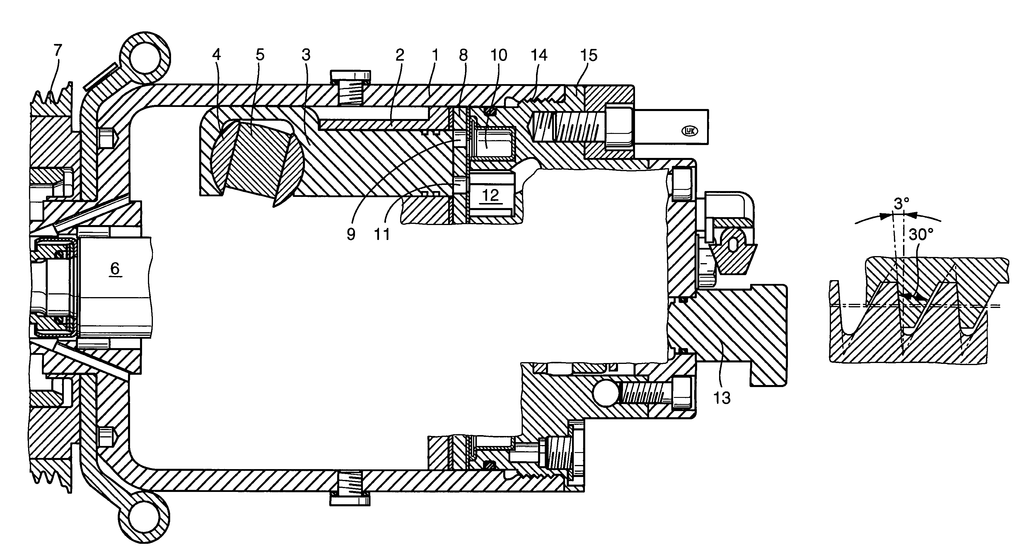
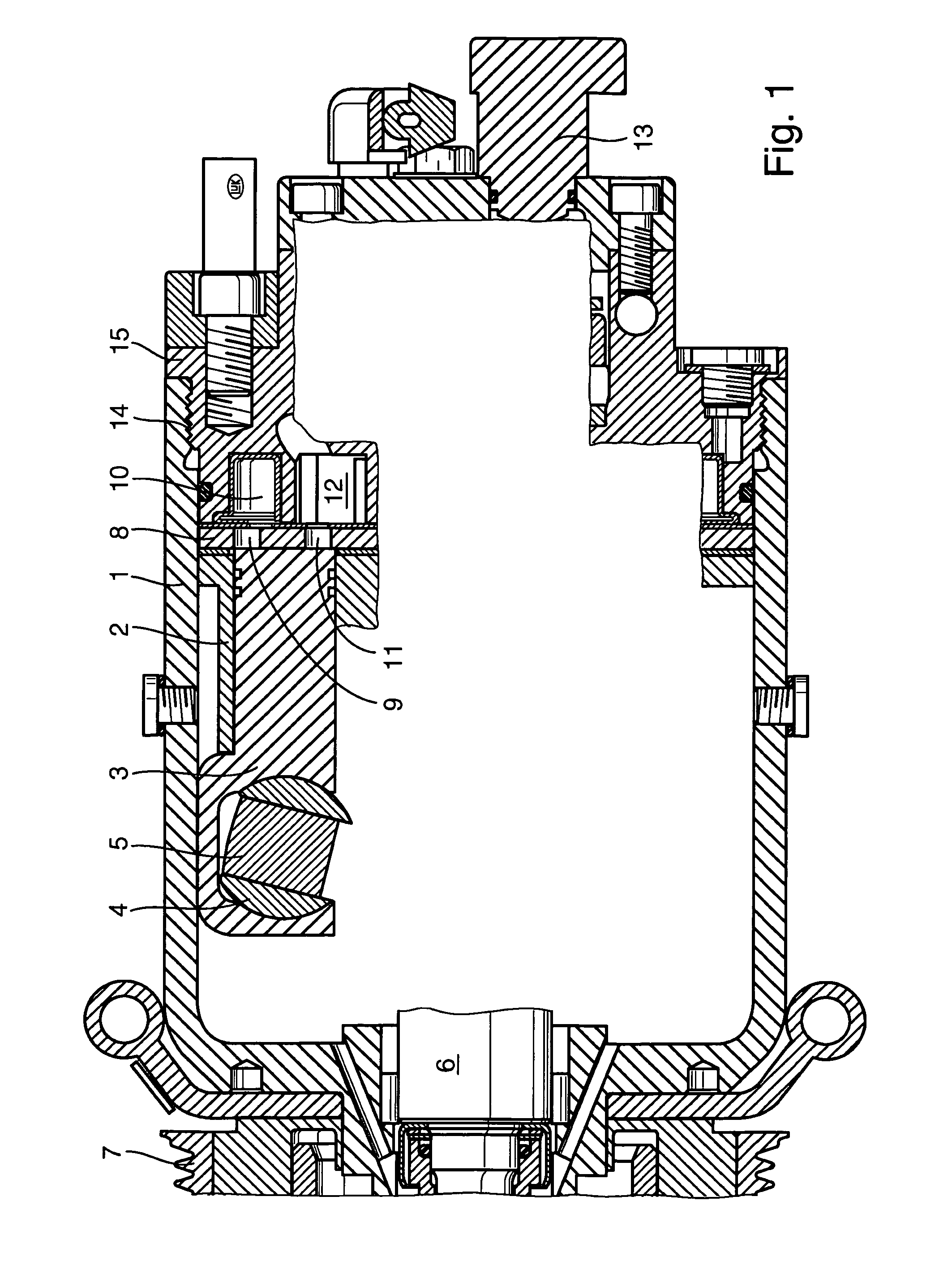
[0021]The housing of an air-conditioner compressor and several of its component parts are shown in cross section in FIG. 1. In a housing 1, which is preferably manufactured from steel or materials having similar strength properties, a piston and crankshaft assembly having a cylinder block 2 is accommodated, in which reciprocating pistons 3 suction and compress refrigerant, and discharge it again under pressure. Pistons 3 are coupled via piston shoes 4 to a drive device in the form of a pivot plate or a pivot ring 5. Pivot ring 5 is set into rotation by a drive shaft 6 via a driver (not shown). Pivot ring 5 may assume various pivoting angle positions and thus vary the piston displacement of the compressor. Drive shaft 6 is driven via a belt pulley device 7 in the belt drive of a combustion engine, as is customary for air-conditioner compressors used in motor vehicles.

[0022]Above cylinder block 2, a valve plate 8 having suction and discharge valves (not shown in detail here) is accomm...


PUM


Abstract

A reciprocating piston machine, in particular a compressor, such as for the air conditioning system of an automotive vehicle. The machine includes a casing and at least one casing cover. A working unit including pistons and is arranged or formed in the casing. The intake and exhaust zone or a front shaft bearing are arranged or formed in the casing cover (covers). The casing cover is screwed on the casing. The screw assembling is carried out with the aid of ring nuts or saw tooth screw threads between the casing and the casing cover, wherein the casing and cover are made of materials with different strengths and different thermal expansion coefficients.

Description

[0001]The present invention is directed to a reciprocating piston machine, in particular a compressor, preferably for the air conditioning system of a motor vehicle, having a housing and at least one housing cover, the power unit encompassing the pistons being accommodated or formed in the housing, and the suction and discharge areas or a forward shaft bearing being accommodated or formed in the housing cover, and the housing cover being screw-coupled to the housing.BACKGROUND[0002]Reciprocating piston-type machines of the type described are generally known. In this context, it may be a question of a compressor, thus, for example, of a compressor for the air conditioning system of a motor vehicle. Compressors of this kind are usually referred to as air-conditioner compressors, and include a housing, which encompasses an externally driven compressor unit or pump unit. The compressor unit designed, for example, as an axial piston machine, includes, in turn, at least one piston which i...

Claims


Application Information

Patent Timeline
Patent Type & Authority Patents(United States)
IPC IPC(8): F01B3/02F04B39/12F04B27/08F04B27/10
CPCF04B27/1081
Inventor WEBER, GEORGHINRICHS, JAN
Owner LUK FAHRZEUG HYDRAULIK
Why Eureka
Try Eureka