
Photosensitive silane coupling agent, method of modifying surface, method of forming pattern, and method of fabricating device

a technology of photosensitive silane and coupling agent, which is applied in the direction of photosensitive materials, instruments, photomechanical equipment, etc., can solve the problems of increasing the size of equipment, many problems that need to be resolved, and the limitation of the light diffraction limit for the resolution of reduced projection exposur

Inactive Publication Date: 2010-04-27
CANON KK
View PDF27 Cites 0 Cited by
  • Summary
  • Abstract
  • Description
  • Claims
  • Application Information

AI Technical Summary

Benefits of technology

The present invention is related to a photosensitive silane coupling agent that can be used to modify surfaces and form microparticle patterns. The photosensitive silane coupling agent includes a 1,2-naphthoquinone-2-diazido-5-sulfonyl group or a 1,2-naphthoquinone-2-diazido-4-sulfonyl group. The photosensitive silane coupling agent can be layered onto a surface and exposed to radiation to generate a carboxyl group. The carboxyl group can then be used to selectively arrange microparticles on the exposed or unexposed portions of the surface. The invention also includes a method of fabricating a device using the patterning method. The technical effects of the invention include improved surface modification and patterning capabilities.

Problems solved by technology

However, the resolution of reduced projection exposure is limited by the light diffraction limit, which is about one-third the wavelength of the light source.
Thus, although photolithography continues to have improving fineness, many problems needing to be resolved have arisen, such as the increased size of the equipment resulting from shortening the wavelength of the light source, as well as development of lenses for such wavelength region, equipment costs and costs of the corresponding lenses.
However, because these devices require even greater high-precision microfabrication techniques than those for semiconductor devices, mass production has been difficult with conventional photolithography techniques.
Further, in Japanese Patent Application Laid-Open No. 2003-168606, there is the problem of a high rate of defects due to the microparticles not properly adhering to the energy beam irradiation portion.

Method used


Image

  • Photosensitive silane coupling agent, method of modifying surface, method of forming pattern, and method of fabricating device
  • Photosensitive silane coupling agent, method of modifying surface, method of forming pattern, and method of fabricating device
  • Photosensitive silane coupling agent, method of modifying surface, method of forming pattern, and method of fabricating device

Examples


examples

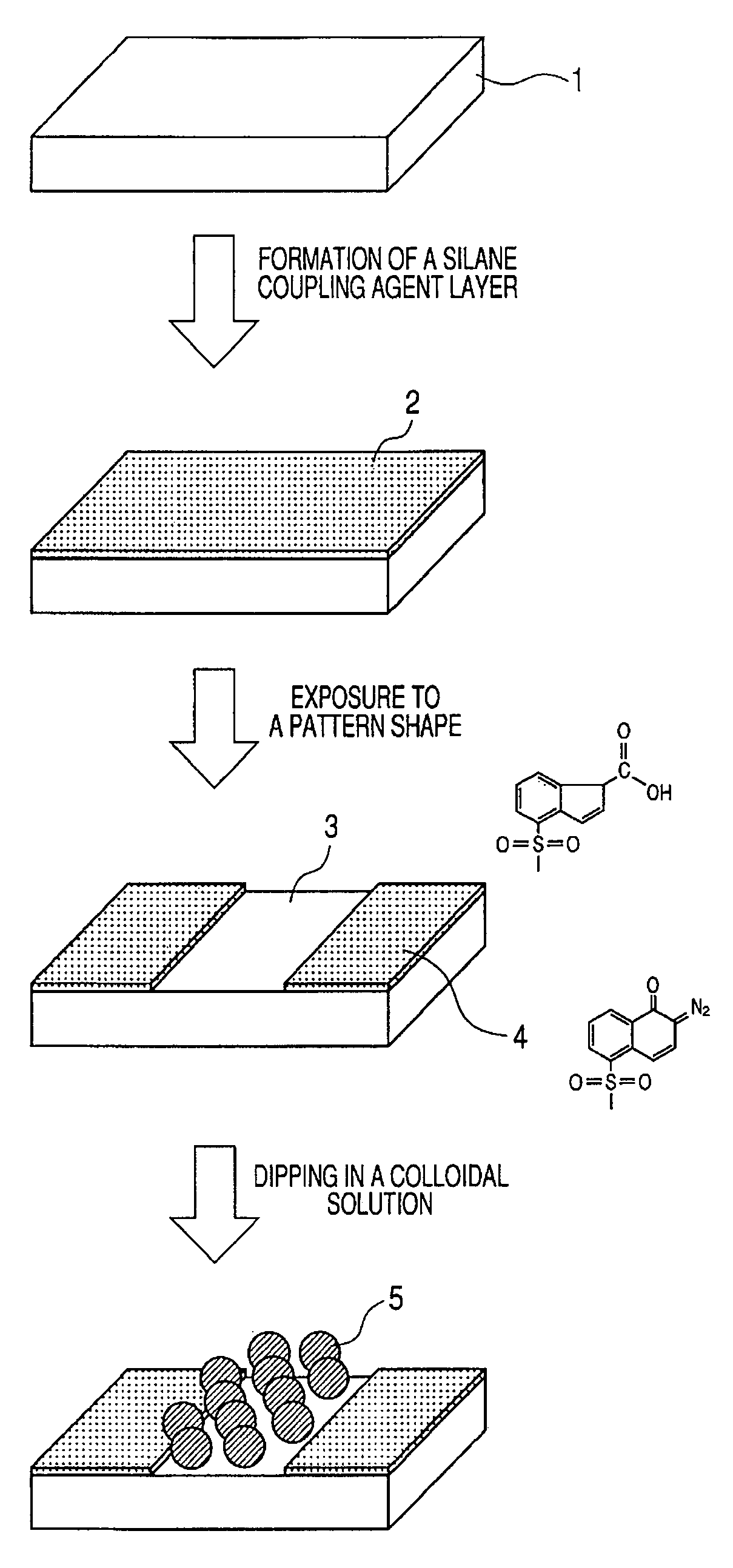
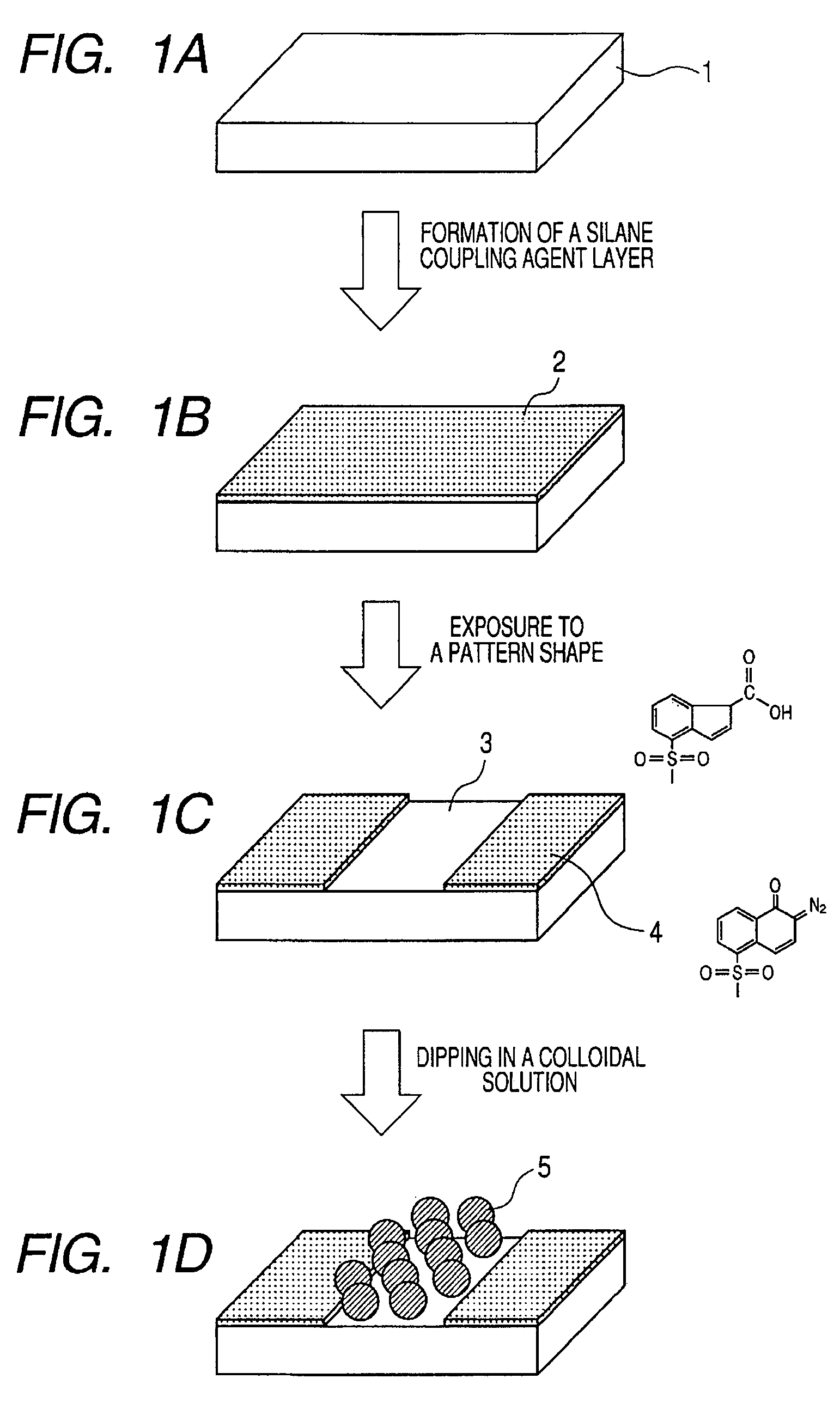
[0082]The method of forming a pattern using the above-described photosensitive silane coupling agent will now be described in more detail based on the drawings.

[0083]FIGS. 1A, 1B, 1C and 1D are a process chart illustrating one embodiment of a method for forming a pattern using the photosensitive silane coupling agent according to the present invention.

[0084]The photosensitive silane coupling agent according to the present invention is immobilized on a substrate via a chemical bond. Examples of the substrate include a metal substrate, a semiconductor substrate, an insulating substrate such as glass, quartz, BN or the like. In addition, the substrate can be selected depending on the desired device from among a broad range of substrates having, for example, one or plural kinds of resist, spin-on-glass, metal, oxide, nitride or the like formed as a film on the above-described substrates. Preferably, a hydroxyl group is formed on the surface immobilizing the photosensitive silane couplin...


PUM

PropertyMeasurementUnit
particle diameteraaaaaaaaaa
wavelengthsaaaaaaaaaa

Abstract

Provided are a photosensitive silane coupling agent for forming a low-defect microparticle pattern, dot array pattern, or hole array pattern through fewer steps, and a method of forming a pattern using such photosensitive silane coupling agent. Used is a photosensitive silane coupling agent comprising a 1,2-naphthoquinone-2-diazido-5-sulfonyl group or a 1,2-naphthoquinone-2-diazido-4-sulfonyl group.

Description

BACKGROUND OF THE INVENTION[0001]1. Field of the Invention[0002]The present invention relates to a photosensitive silane-coupling agent, a method of modifying a surface and a method of forming a pattern using such photosensitive silane coupling agent, and a method of fabricating a device.[0003]2. Description of the Related Art[0004]Recently, in the fields of various electronic devices which require microfabrication, such as semiconductor devices, there has been ever increasing demands for increased density and integration of the devices. In the step of fabricating a semiconductor device, it is the photolithography process that plays an important part in forming the fine circuit pattern.[0005]Most current photolithography processes are carried out by reduced projection exposure. However, the resolution of reduced projection exposure is limited by the light diffraction limit, which is about one-third the wavelength of the light source. Thus, attempts have been made to achieve shorter ...

Claims


Application Information

Patent Timeline
Patent Type & Authority Patents(United States)
IPC IPC(8): G03F7/00G03F7/004
CPCC07F7/12C07F7/1836G03F7/0751G03F7/0755G03F7/165G03F7/022C07F7/1804
Inventor ITO, TOSHIKIMIZUTANI, NATSUHIKOYAMAGUCHI, TAKAKOINAO, YASUHISA
Owner CANON KK
Learn More