Microbolometer infrared detector elements and methods for forming same

a microbolometer and infrared detector technology, applied in the field of infrared detectors, can solve the problems of high resistance which is difficult to match with input impedance, and achieve the effect of promoting stable atomic configuration of amorphous silicon film

Active Publication Date: 2010-05-18
DRS NETWORK & IMAGING SYST
View PDF88 Cites 34 Cited by
  • Summary
  • Abstract
  • Description
  • Claims
  • Application Information

AI Technical Summary

Benefits of technology

[0011]In one embodiment, the disclosed microbolometer infrared detector elements may be formed using a hydrogen-dilution process in which hydrogen (H2) precursor is used to dilute other precursor materials, including those described elsewhere herein, to form amorphous silicon-based microbolometer membrane structures having improved stability and performance characteristics. Although not wishing to be bound by theory, it is believed that this improved stability and performance results from the effects that H2 has on reaction and / or reaction kinetics of the amorphous silicon-based material formation process. Hydrogen dilution may be employed in the formation of thin films of amorphous silicon-based materials that include varying amounts of one or more additional materials, such as fluorine, germanium, n-type dopants, p-type dopants, etc. As an example, a microbolometer membrane structure including a-Si:H may be formed by the addition of hydrogen gas to a chemical vapor deposition (CVD) reactor, such as PECVD reactor, to dilute silane gas during membrane fabrication. Advantageously, hydrogen dilution of silane results in the growth of hydrogenated amorphous silicon (a-Si:H) which exhibits improved properties such as lower electrical noise, higher temperature coefficient of resistance (TCR) and more stable atomic configuration. In one exemplary embodiment, hydrogenated amorphous silicon having a thickness of about 600 Angstrom may be formed in a PECVD reactor using a dilution ratio of about 10:1 (i.e., about 10 parts hydrogen gas to about one part silane gas) to fabricate a microbolometer membrane structure that exhibits a reduction in noise by a factor of greater than about three (alternatively by a factor of greater than about four), in comparison to a amorphous silicon microbolometer membrane structure similarly formed but with no hydrogen dilution.

Problems solved by technology

Low doped material results in high resistance which is difficult to match with the input impedance of ROICs operating at ambient temperature.

Method used


Image

  • Microbolometer infrared detector elements and methods for forming same
  • Microbolometer infrared detector elements and methods for forming same
  • Microbolometer infrared detector elements and methods for forming same

Examples


Embodiment Construction

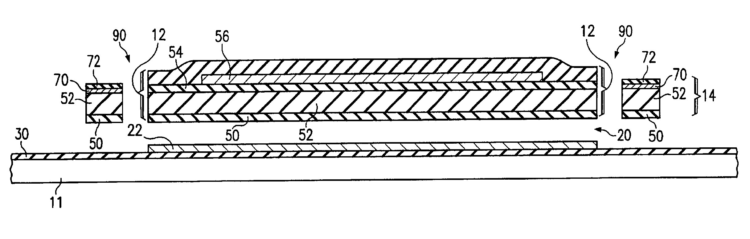
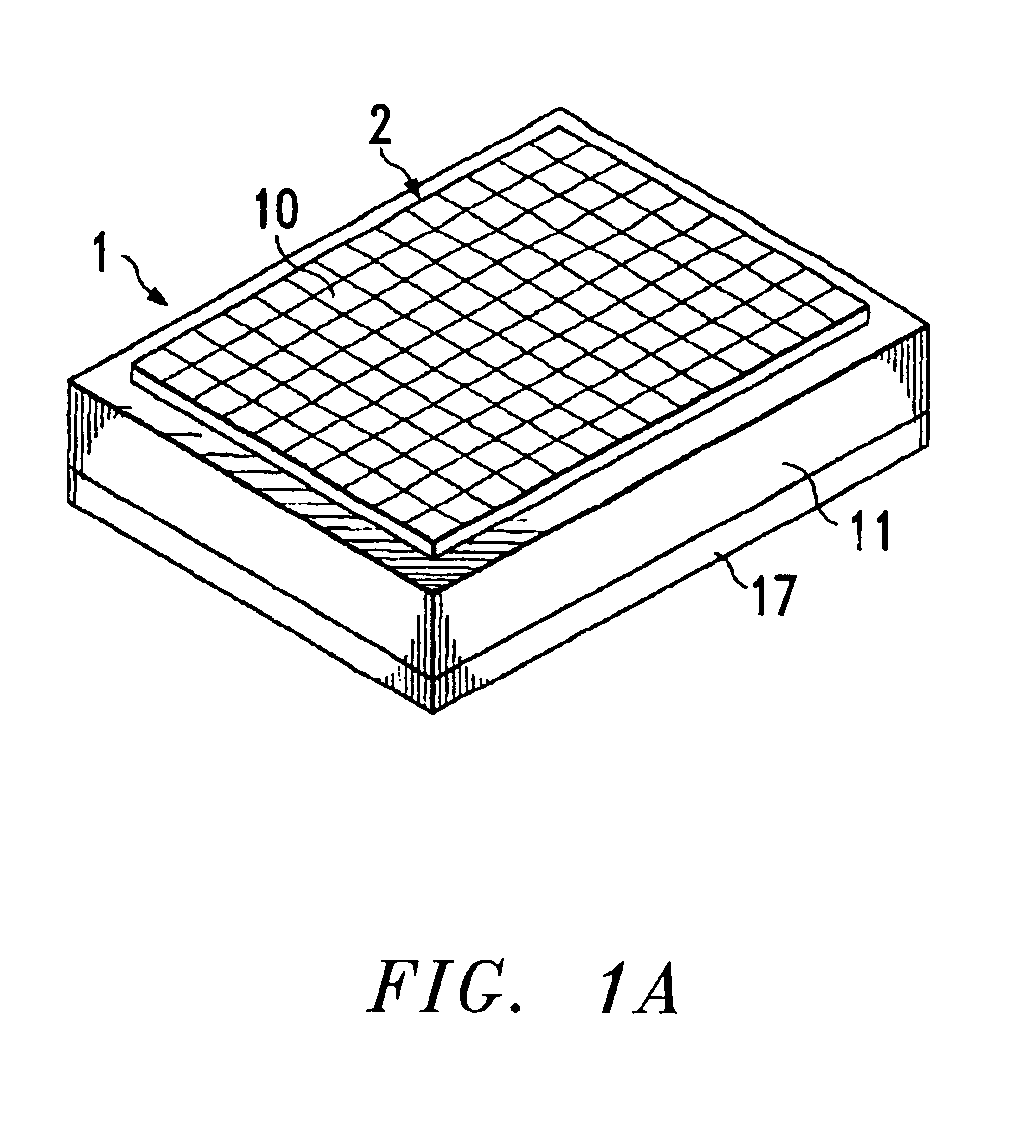
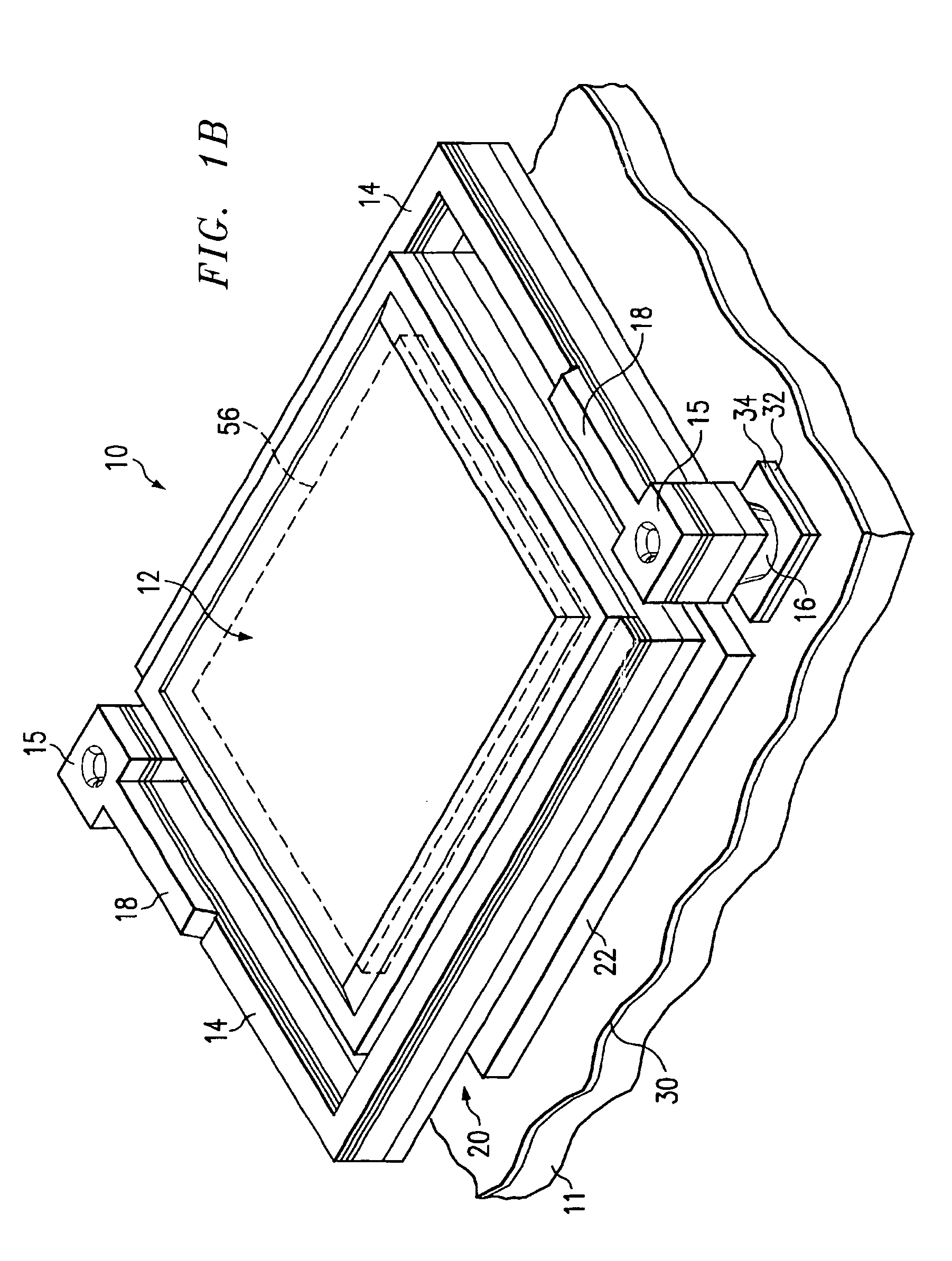
[0047]FIG. 1A is a diagrammatic perspective view of one embodiment of an infrared detector 1 which is capable of sensing thermal energy and of outputting electrical signals representative of a two-dimensional image of that sensed thermal energy. The infrared detector 1 includes a focal plane array 2 disposed on a substrate 11. The substrate 11 may include an integrated circuit of a type which is commonly known as a read out integrated circuit (ROIC). The ROIC reads out the thermal information gathered by the focal plane array 12.

[0048]A thermal element 17 may be optionally provided on the side of the substrate 16 opposite from the focal plane array 2, in order to serve as a form of controlled heat sink which maintains the integrated circuit substrate 11 at a substantially constant temperature which is predefined. The constant temperature prevents ambient or internally generated temperature gradients from affecting operation of the focal plane 2, and thus provides a baseline with whi...


PUM

PropertyMeasurementUnit
sizeaaaaaaaaaa
temperatureaaaaaaaaaa
wavelength rangeaaaaaaaaaa

Abstract

Microbolometer infrared detector elements that may be formed and implemented by varying type / s of precursors used to form amorphous silicon-based microbolometer membrane material / s and / or by varying composition of the final amorphous silicon-based microbolometer membrane material / s (e.g., by adjusting alloy composition) to vary the material properties such as activation energy and carrier mobility. The amorphous silicon-based microbolometer membrane material / s materials may include varying amounts of one or more additional and optional materials, including hydrogen, fluorine, germanium, n-type dopants and p-type dopants.

Description

FIELD OF THE INVENTION[0001]This invention relates in general to infrared detectors and more particularly to microbolometer infrared detector elements and methods for forming the same.BACKGROUND OF THE INVENTION[0002]Infrared (IR) detectors are often utilized to detect fires, overheating machinery, planes, vehicles, people, and any other objects that emit thermal radiation. Infrared detectors are unaffected by ambient light conditions or particulate matter in the air such as smoke or fog. Thus, infrared detectors have potential use in night vision and when poor vision conditions exist, such as when normal vision is obscured by smoke or fog. IR detectors are also used in non-imaging applications such as radiometers, gas detectors, and other IR sensors.[0003]Infrared detectors generally operate by detecting the differences in thermal radiance of various objects in a scene. That difference is converted into an electrical signal which is then processed. Microbolometers are infrared radi...

Claims


Application Information

Patent Timeline
Patent Type & Authority Patents(United States)
IPC IPC(8): G01J5/02
CPCG01J5/02G01J5/023G01J5/20G01J5/046G01J5/04
Inventor SYLLAIOS, ATHANASIOS J.SCHIMERT, THOMAS R.TAYLOR, MICHAEL F.
Owner DRS NETWORK & IMAGING SYST
Why Eureka
Try Eureka