
Method and apparatus for combining continuous wave and time domain optical imaging

Inactive Publication Date: 2010-05-18
SOFTSCAN HEALTHCARE GROUP +1
View PDF19 Cites 3 Cited by
  • Summary
  • Abstract
  • Description
  • Claims
  • Application Information

AI Technical Summary

Benefits of technology

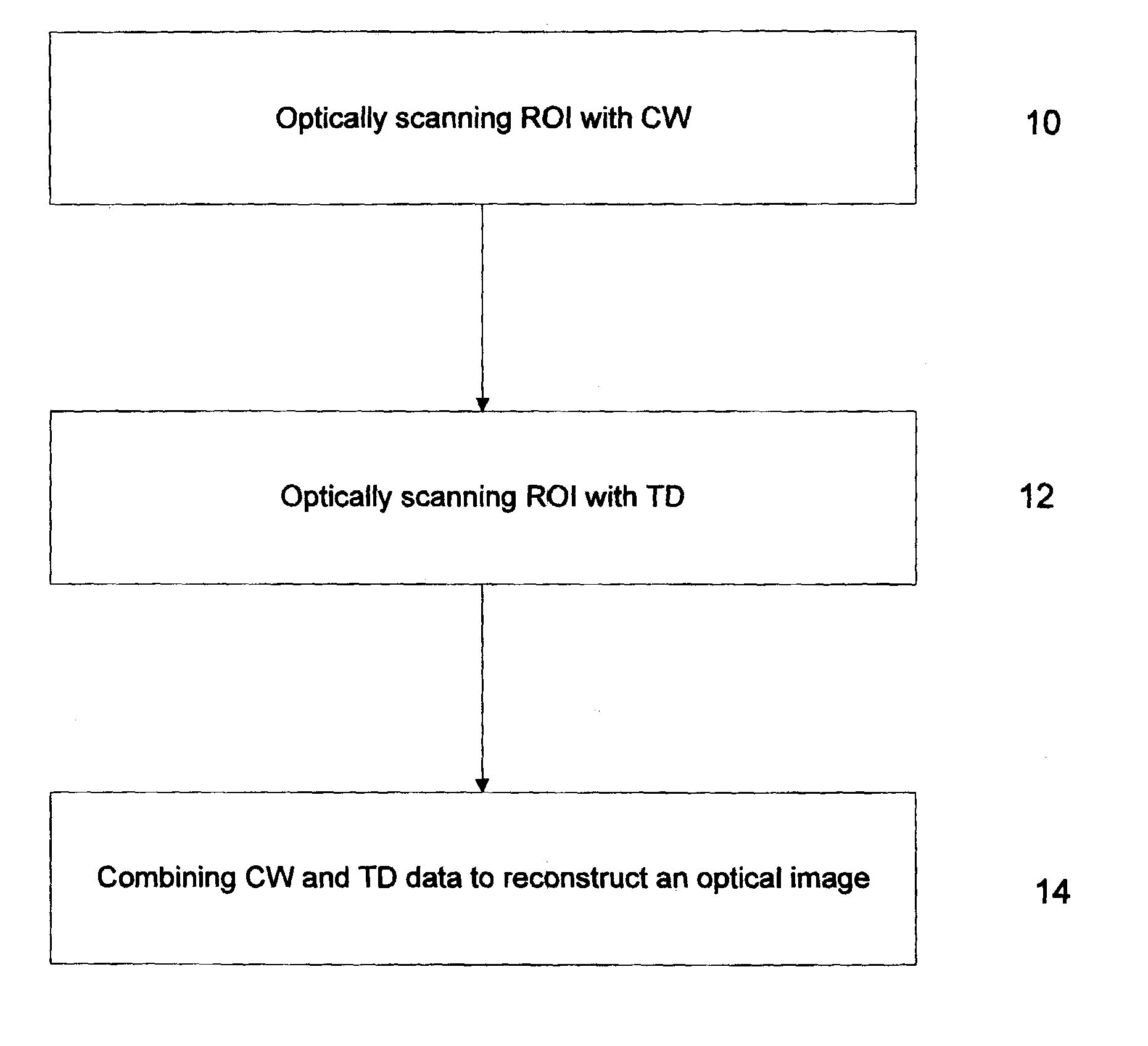
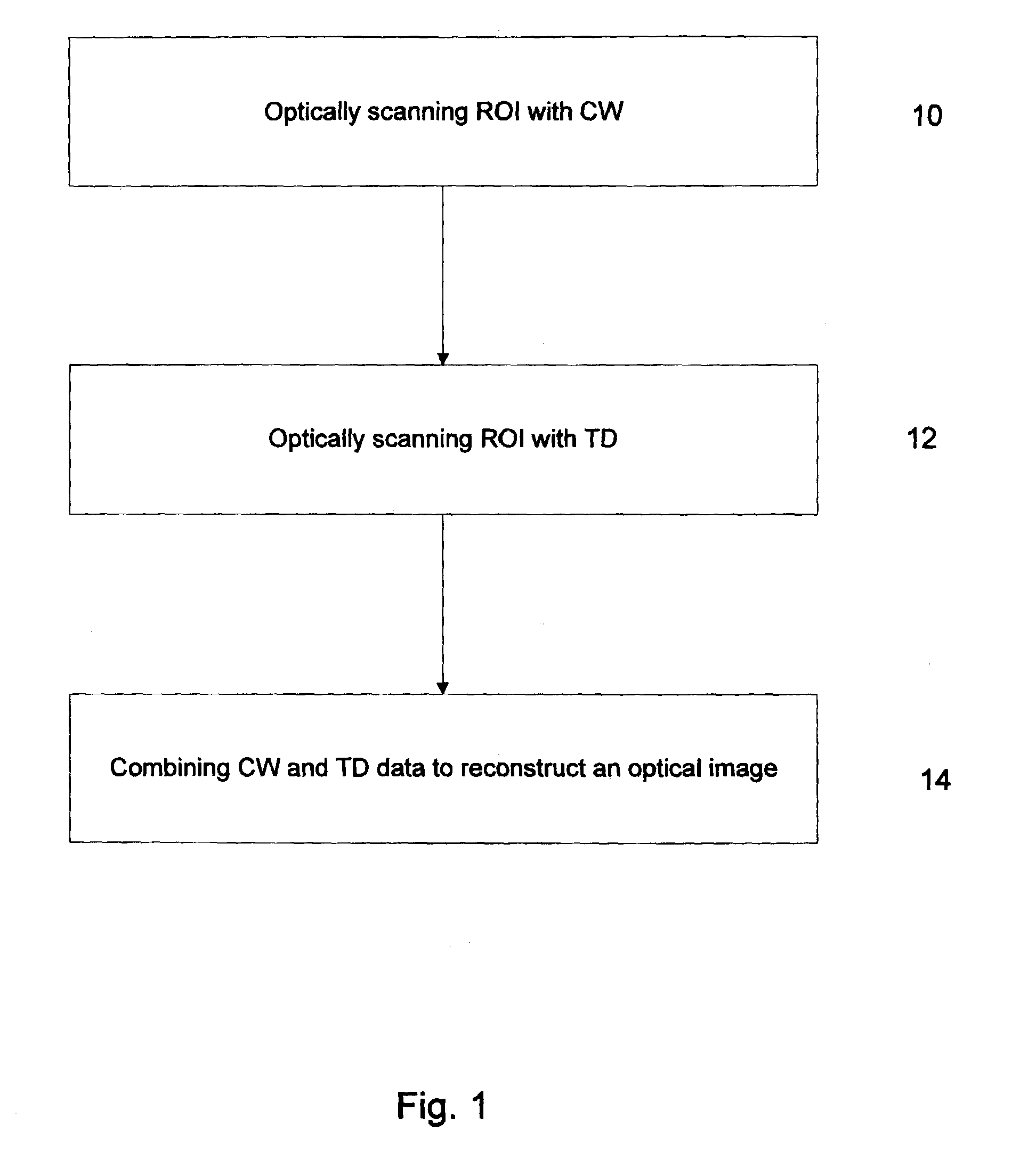
[0009]The inventor has provided a method and apparatus by which the advantages of TD optical imaging can be exploited while avoiding certain disadvantages. In particular long acquisition times can be substantially reduced.
[0013]combining information provided by CW and TD, whereby to generate an improved image of the VOI with fewer light pulses and a shorter acquisition time by using both time-domain and continuous wave modalities.
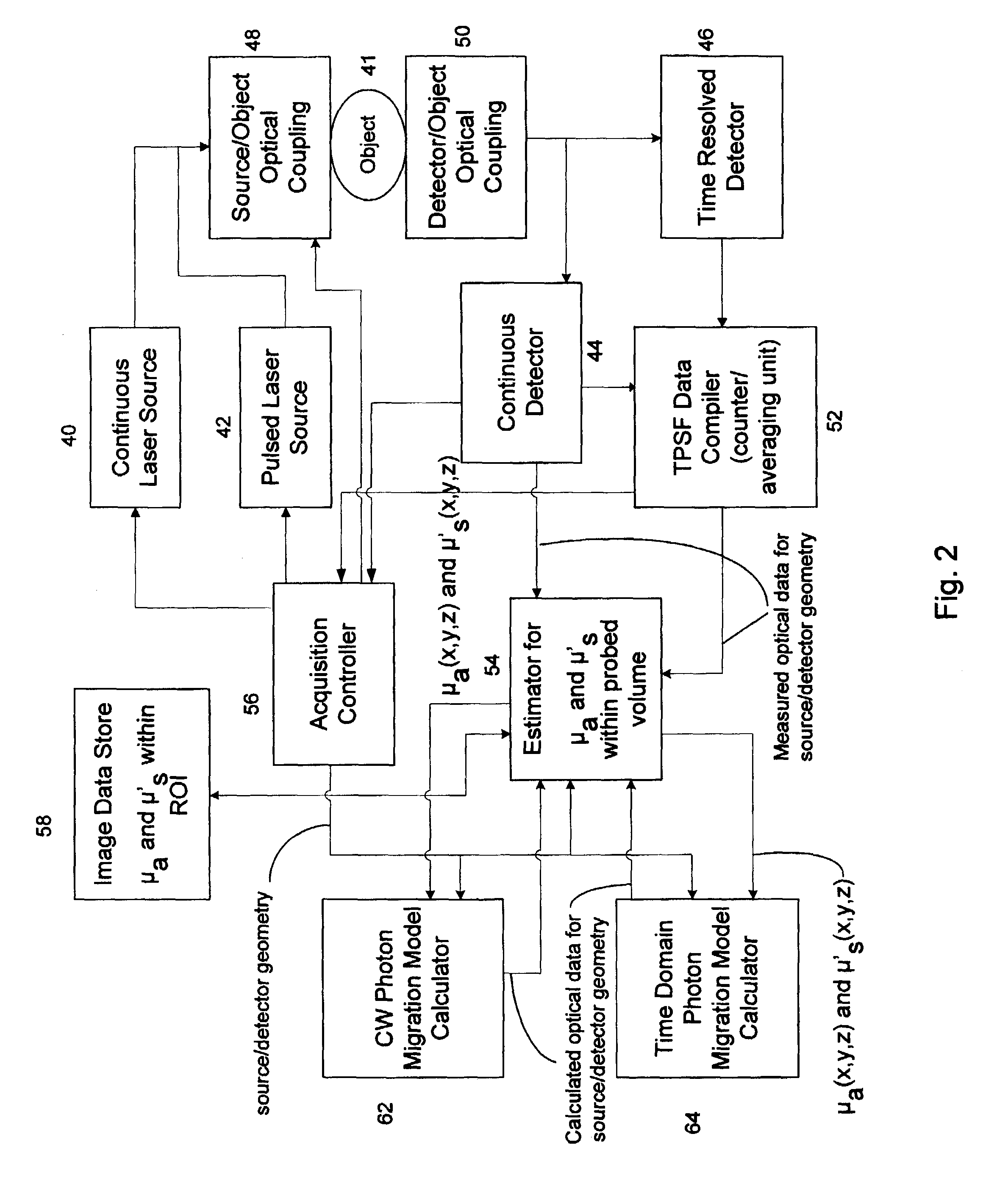
[0015]It will be appreciated that the present invention allows for a number of different possible economies to be achieved by combining CW with TD techniques. Firstly, the estimate of absorption coefficients for a VOI from CW (making an assumption about scatter, such as assuming that scatter is constant for example) can be used as initial values in processing the TD data to yield more accurate absorption coefficients (along with scatter coefficients). Secondly, the process of determining the optical properties of the VOI can involve simultaneously comparing CW model data with CW measured data and comparing TD model data with TD measured data. Thirdly, processing time and acquisition time can be reduced by using an image generated from CW data alone as a less-accurate image, whose purpose is to help in defining a subset of source / detector configurations or geometries to be used in collecting TD data for specific portions of the VOI requiring better detail.

Problems solved by technology

Continuous wave permits rapid acquisition and is the least expensive of the three approaches but provides a limited amount of information.
The problem consists of finding the distribution of optical parameters in tissue based on the detected optical signal.
TD measurements provide detailed information about the absorption and the scatter from within a tissue, however, the method suffers from long acquisition time, expensive hardware and complicated software analysis.
Furthermore the acquisition often results in noisy TPSF data from which accurate estimates of spatial optical information are difficult to obtain.

Method used


Image

  • Method and apparatus for combining continuous wave and time domain optical imaging
  • Method and apparatus for combining continuous wave and time domain optical imaging
  • Method and apparatus for combining continuous wave and time domain optical imaging

Examples


Embodiment Construction

[0022]In the present description, by CW measurements it is meant optical signals measured while the light source that illuminates the object to be imaged is continuously on, namely a steady state flux measurement.

[0023]By Time Domain (TD) measurements, it is meant that the optical signal is measured as a function of time following a brief pulse of the light source. The resulting signal is the so-called temporal point spread function (TPSF), and the TPSF data collected may be either one, two, a few or several points on the TPSF (often referred to as different time gates), a single parameter resulting from a plurality of points, such as a slope or other characteristic of the TPSF curve, or the whole TPSF data. When the TD optical detector is a single-photon counting detector, the whole TPSF can be efficiently collected as a result of the measurement technique. When a gated ICCD is used, it is more practical to select time gates. Due to the nature of the detection system, the TPSF data...


PUM


Abstract

There is provided methods and systems for optical imaging in a turbid medium that combine continuous wave (CW) and time domain (TD) approaches to substantially increase robustness of optical imaging as well as to reduce acquisition times associated with the TD approach. In one aspect, a method is provided that uses CW measurements to scale the values of a temporal point spread function (TPSF) to avoid physical unit mismatch problems. In another aspect, both CW and TD measurements are synergistically combined to estimate optical properties of the medium used in image reconstruction. Optical systems capable of realizing these methods are also provided.

Description

CROSS-REFERENCE TO RELATED APPLICATIONS[0001]This is the first application filed for the present invention.TECHNICAL FIELD[0002]The invention relates to the field of optical imaging of turbid media, such as mammalian tissue. More specifically, the invention relates to optical imaging using both continuous wave and time domain methods.BACKGROUND OF THE INVENTION[0003]Imaging of mammalian tissues has been used extensively to obtain information on the internal structures as well as on the biodistribution of molecules. This information can of course be utilized for diagnosis purposes. Several techniques based on different physical principles are currently available to obtain images that encompass a broad range of spatio-temporal resolution. Such techniques include Magnetic Resonance Imaging (MRI), Positron Emission Tomography (PET), single-photon emission computed tomography (SPECT), X-ray, ultrasound and, now emerging, optical imaging.[0004]In optical imaging three approaches have been...

Claims


Application Information

Patent Timeline
IPC IPC(8): A61B6/00A61B5/00G01N21/47
CPCG01N21/4795A61B5/0073
Inventor HALL, DAVID JONATHAN
Owner SOFTSCAN HEALTHCARE GROUP
Learn More