Specimen preservation systems and methods

Active Publication Date: 2010-05-25
TED PELLA
View PDF12 Cites 6 Cited by
  • Summary
  • Abstract
  • Description
  • Claims
  • Application Information

AI Technical Summary

Benefits of technology

[0009]At this time, the two parts are rotated so that the sealing O-ring moves above the small hole. This will stop the flow into and out of the container. Thus, the assembly of the bottom and top parts of the container with the hole and the O-ring form the basis of an exhaust valve. After this, the gas inlet valve is closed to seal the inert gas in the container. At this point, the pressure in the cylinder is just slightly above atmospheric pressure because of the low delivery pressure during the purging stage. After the valve is closed, the pressure in the container is increased by screwing the two parts of the container in relation t

Problems solved by technology

Typically, the inventive container is used for the preservation of microscopy or material samples that may undergo changes during the delay between the time the sample is prepared and the time when analysis of the sample occurs, wherein the change in the sample would otherwise adversely affect the results of the analysis.
For example, in optical microscopy, oxidation or reaction with sulfur in the air can lead to color changes seen on the sample that affect the quality and the interpretation of the image.
SEM, TEM, and SPM techniques are surface sensitive and oxidation of the surface can lead to charging effects and/or the inability to examine the sample.
The presence of a modified surface can lead to erroneous interpretation of the images or data acquired from samples that undergo c

Method used


Image

  • Specimen preservation systems and methods
  • Specimen preservation systems and methods
  • Specimen preservation systems and methods

Examples


Embodiment Construction

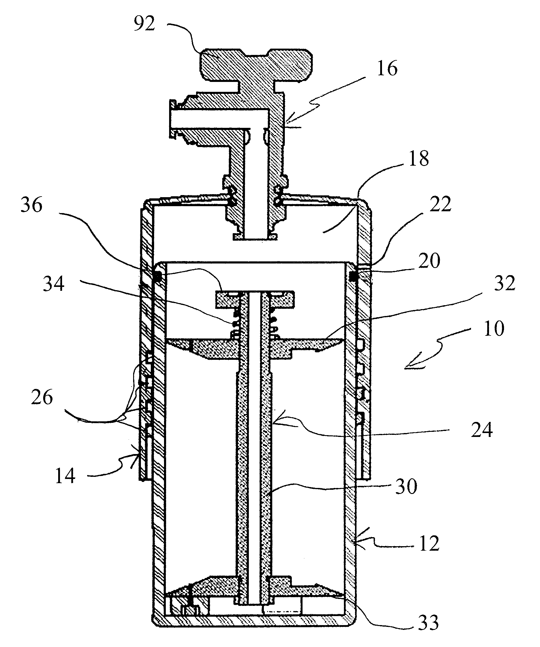
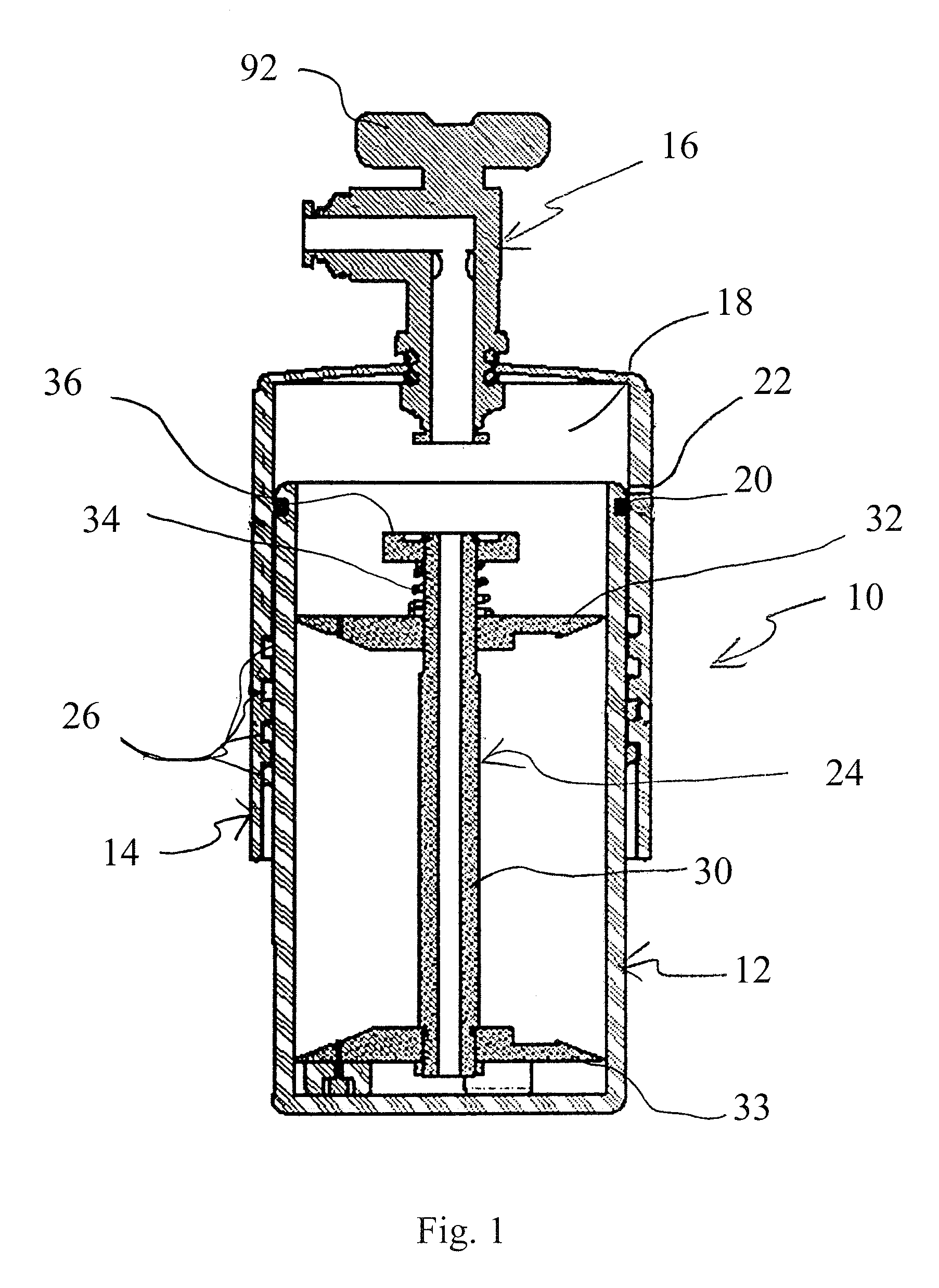
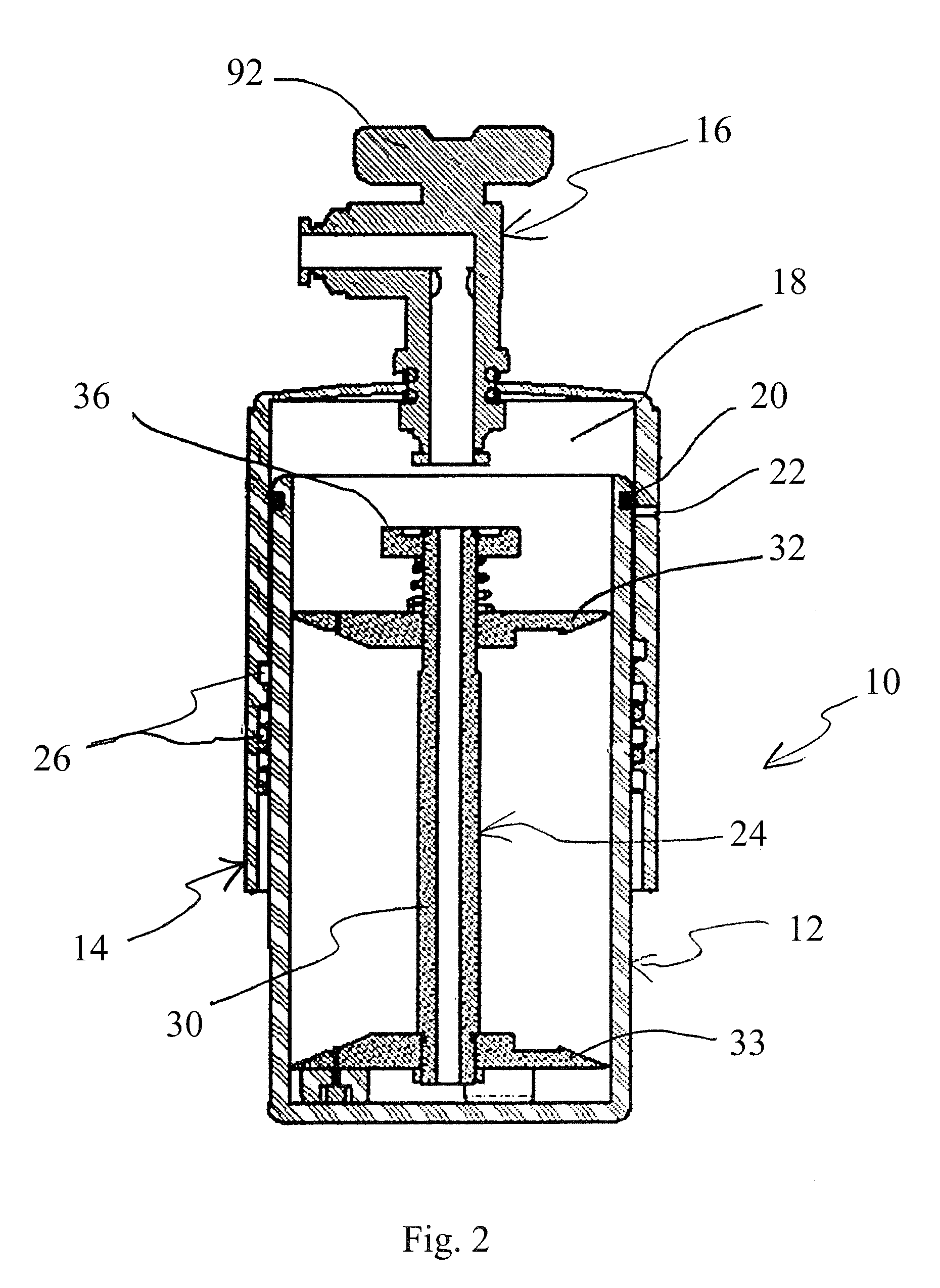
[0032]Referring now more particularly to FIGS. 1-3, there is shown a container 10 which is constructed in accordance with the principles of the present invention. The container 10 comprises a bottom portion 12 and a top portion 14, which are assembled together, as shown in FIG. 1, for example, wherein the bottom portion 12 is telescopically received within the top portion 14. An inlet gas valve 16 provides fluid access to an interior chamber 18 defined by the top portion 14 of the container 10. The valve 16 may be disposed at the non-open end of either the top or bottom cylinder or container portion 14, 12, respectively, though it is preferably located at the top end of the top container portion 14, as shown. A sealing O-ring 20 is disposed between the sidewalls of the top portion 14 and the bottom portion 12 of the container 10. An outlet opening or exhaust aperture 22 is disposed in the sidewall of the top portion 14, as shown in the drawings.

[0033]A sample holder insert 24 is pro...


PUM


Abstract

A two-part container for preserving material samples during storage and transport is separable and can be sealed with the presence of an elastomeric O-ring and internal threads on each part of the container. In the configuration at which the threads first engage between the two halves of the container, there is a small hole in the outer top part just above the O-ring of the bottom mating part. When the two container parts are mated and the sealing O-ring is below the small hole, inert gas can be made to flow through an inlet valve, into the container, and out through the small hole. In this configuration, the inert gas flows through the container and purges the atmospheric gas, replacing it with inert gas. After a period of time, the two container parts are rotated so that the sealing O-ring moves above the small hole. This will stop the flow into and out of the container. After this, the gas inlet valve is closed to seal the inert gas in the container. After the valve is closed, the pressure in the container is increased by screwing the two parts of the container in relation to each other such that the volume of the container is decreased. Prior to opening, the efficacy of the container can be checked by releasing the gas while the container is in the compressed state.

Description

[0001]This application claims the benefit under 35 U.S.C. 119(e) of the filing date of Provisional U.S. Application Ser. No. 60 / 703,727, entitled Specimen Preservation System, and filed on Jul. 29, 2005, which application is expressly incorporated herein by reference.BACKGROUND OF THE INVENTION[0002]This invention relates to a specialized container that allows a process or method of replacing the atmospheric air that is in a container, which is composed of reactive gas species such as oxygen and water vapor, with an inert gas species such as nitrogen, carbon dioxide, argon, and the like, so that a material or the surface of the material disposed in the container does not undergo reactions such as oxidation during storage and / or transportation. Typically, the inventive container is used for the preservation of microscopy or material samples that may undergo changes during the delay between the time the sample is prepared and the time when analysis of the sample occurs, wherein the ch...

Claims


Application Information

Patent Timeline
IPC IPC(8): G01F23/00B65D6/00B65D8/14G21K5/08G21K5/10
CPCB01L3/508A01N1/0263G01N1/28B01L2200/141B01L2200/185B01L2300/049B01L2300/14G01N1/44B01L2300/10
Inventor WALCK, SCOTT D.
Owner TED PELLA
Why Eureka
Try Eureka