Solid electrolytic capacitor and manufacturing method thereof

a technology of electrolyte capacitor and solid electrolytic capacitor, which is applied in the direction of variable capacitor, fixed capacitor, fixed capacitor details, etc., can solve the problem of not getting sufficient esr, achieve good adhesion property to carbon, improve the adhesion property and reduce the contact resistance between the electrolyte layer and the cathode

Active Publication Date: 2010-06-22
SANYO ELECTRIC CO LTD
View PDF14 Cites 0 Cited by
  • Summary
  • Abstract
  • Description
  • Claims
  • Application Information

AI Technical Summary

Benefits of technology

[0009]Another object of the present invention is to provide a method of manufacturing a solid electrolytic capacitor with low equivalent serial resistance.
[0022]In the method of manufacturing the solid electrolytic capacitor according to the second aspect, the aqueous solution preferably includes at least one kind of the organic silane selected from the group containing aminopropyltriethoxysilane (APTES), dimethoxydiphenylsilane (DMDPS) and mercaptopropyltrimethoxysilane (MPTMS). According to this structure, the adhesion property between the electrolyte layer and the cathode is further improved. Thus, the contact resistance between the electrolyte layer and the cathode is further reduced and the solid electrolytic capacitor with low ESR is further easily obtained.

Problems solved by technology

However, in the aforementioned conventional solid electrolytic capacitor having the intermediate layer mixed with the dielectric layer and carbon particles formed between the aforementioned dielectric layer and the first conductive layer containing carbon particles, there has remained a problem that an ESR sufficiently low is not obtained.

Method used


Image

  • Solid electrolytic capacitor and manufacturing method thereof
  • Solid electrolytic capacitor and manufacturing method thereof

Examples


example 1

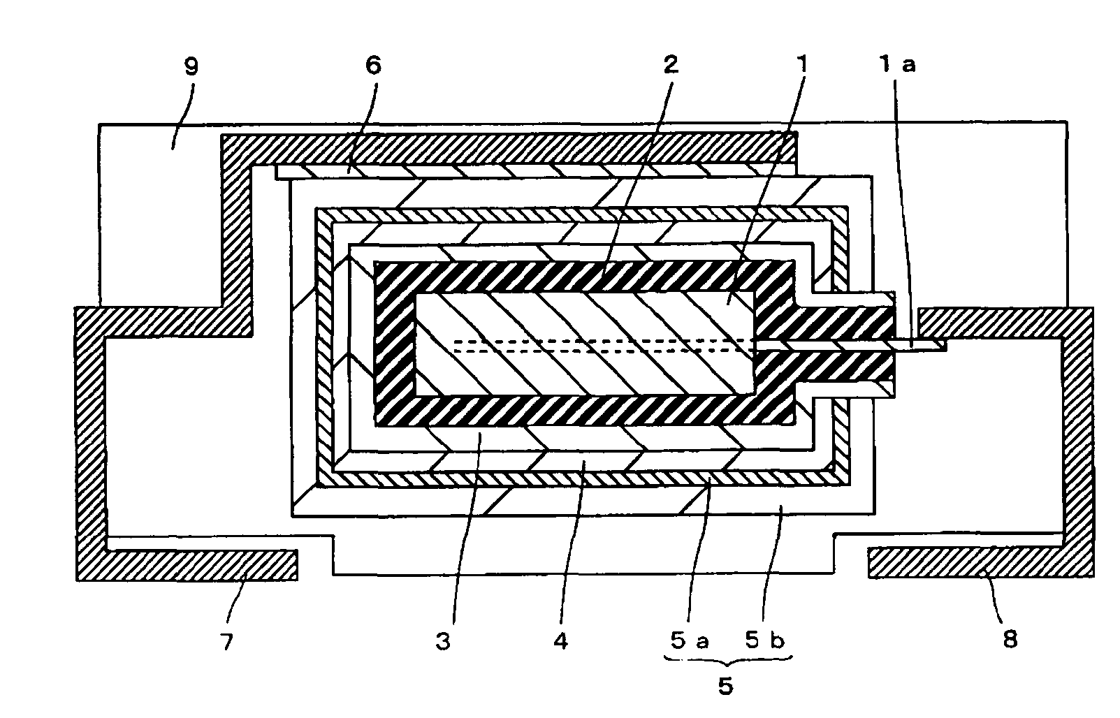
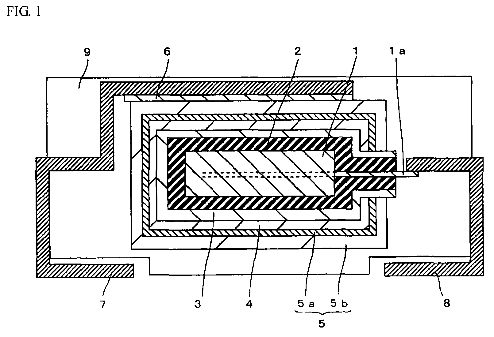
[0025]A structure of a solid electrolytic capacitor according to example 1 of the present invention is now described with reference to FIG. 1.

[0026]First, in the solid electrolytic capacitor according to example 1 of the present invention, a plate-shaped anode 1 is formed for covering the one part of an anode lead 1a of tantalum, as shown in FIG. 1. The anode 1 has a porous sintered body of tantalum prepared by sintering tantalum particles having an average particle diameter of about 2 μm in a vacuum. Tantalum is an example of the “metal” forming the anode in the present invention.

[0027]A dielectric layer 2 of tantalum oxide is formed for covering the anode 1. An electrolyte layer 3 of polypyrrole is formed for covering the dielectric layer 2.

[0028]An intermediate layer 4 of aminopropyltriethoxysilane (APTES) having a thickness of an approximately monomolecular layer (about 0.5 nm) is formed uniformly for covering the electrolyte layer 3. APTES is an example of “organic silane” in t...

example 2

[0047]In example 2, solid electrolytic capacitors having the same structure as that in example 1 are fabricated except that an intermediate layer 4 of another organic silane is formed instead of the intermediate layer 4 of APTES in the aforementioned example 1.

[0048]In this example, the solid electrolytic capacitors are fabricated in the same manner as in example 1, except that aqueous solutions are formed of about 0.002 wt % of octadecyltriethoxysilane (OTES), n-propyltrichlorosilane (nPTCS), dimethoxydiphenylsilane (DMDPS), methylphenyidichlorosilane (MPDCS) and mercaptopropyltrimethoxysilane (MPTMS) respectively, instead of the aqueous solution containing about 0.002 wt % of APTES used in example 1. Thus, the solid electrolytic capacitors having the intermediate layer 4 of OTES, nPTCS, DMDPS, MPDCS and MPTMS with a thickness of an approximately monomolecular layer (about 0.1 nm to about 2.0 nm) disposed between the electrolyte layer 3 and the cathode 5 are fabricated respectively...


PUM

PropertyMeasurementUnit
thicknessaaaaaaaaaa
particle diameteraaaaaaaaaa
thicknessaaaaaaaaaa

Abstract

In this solid electrolytic capacitor, a plate-shaped anode having a porous sintered body, a dielectric layer and an electrolyte layer of polypyrrole are formed in this order for covering one part of an anode lead. An intermediate layer of aminopropyltriethoxysilane (APTES) is formed for covering the electrolyte layer. A cathode having a first conductive layer containing graphite particles and a second conductive layer containing silver particles is formed for covering the intermediate layer. The cathode and a cathode terminal are connected by a conductive adhesive layer. The anode lead and the anode terminal are connected by welding. Further, a mold outer resin is formed to allow one end of the cathode terminal and one end of the anode terminal to project therefrom.

Description

RELATED APPLICATION[0001]The priority application number Japanese patent application No. 2005-96535 upon which this patent application is based is hereby incorporated by reference.BACKGROUND OF THE INVENTION[0002]1. Field of the Invention[0003]The present invention relates to a solid electrolytic capacitor and a method of manufacturing the same.[0004]2. Description of the Background Art[0005]Recently, it has been desired to develop a solid electrolytic capacitor having a smaller value of equivalent serial resistance (hereinafter referred to as ESR) in a high frequency region. In the conventional solid electrolytic capacitor, a dielectric layer is formed on an anode made up of a valve metal such as tantalum for covering the anode by anodic oxidation. Then an electrolyte layer made up of manganese oxide or conductive polymer with low resistivity is formed on the dielectric layer. Further, a cathode having a two-layer structure of a first conductive layer containing carbon particles fo...

Claims


Application Information

Patent Timeline
Patent Type & Authority Patents(United States)
IPC IPC(8): H01G9/04H01G9/145H01G4/06
CPCH01G9/022H01G9/042H01G11/48Y10T29/417Y02E60/13
Inventor IIDA, TAKAHISAYANO, MUTSUMIKIMOTO, MAMORU
Owner SANYO ELECTRIC CO LTD
Why Eureka
Try Eureka