
Broadband light source device

a light source device and broadband technology, applied in the direction of instruments, optical elements, optics, etc., can solve the problems of distorted waveform of output light, lower wavelength conversion efficiency, and increase in cost, and achieve the effect of high intensity and stable shap

Active Publication Date: 2010-06-29
SUMITOMO ELECTRIC IND LTD
View PDF3 Cites 10 Cited by
  • Summary
  • Abstract
  • Description
  • Claims
  • Application Information

AI Technical Summary

Benefits of technology

[0006]Accordingly, it is an object of the present invention to provide a broadband light source device that can generate SC light in a visible range and having a spectrum with a stable shape and high intensity.

Problems solved by technology

This unfavorably leads to problems such as an increase in cost and a distorted waveform of the output light.
A distorted waveform of the output laser beam (i.e. an incident beam on a PCF) leads to a lower wavelength conversion efficiency, thus making it difficult to obtain high-intensity and stable SC light.

Method used


Image

  • Broadband light source device
  • Broadband light source device
  • Broadband light source device

Examples


first embodiment

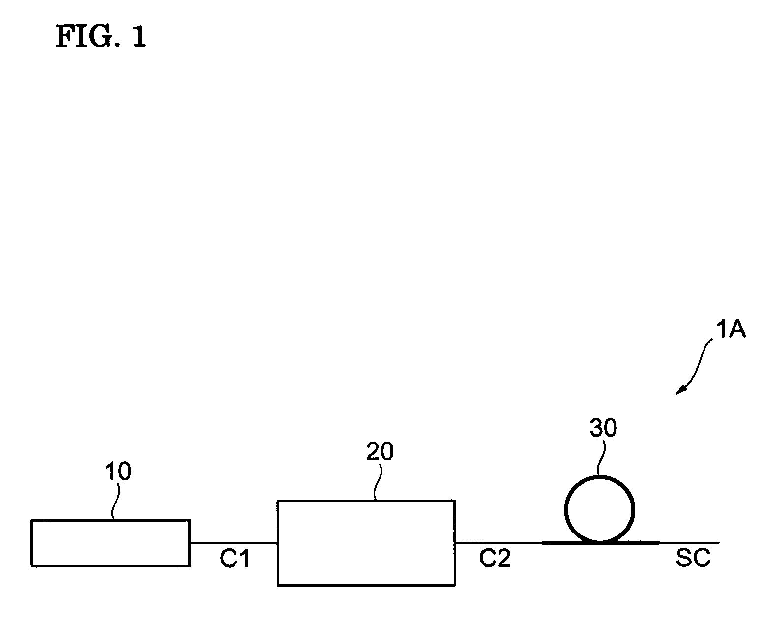
[0015]FIG. 1 schematically illustrates a broadband light source device 1A according to a first embodiment of the present invention. The broadband light source device 1A includes a diode-pumped solid-state laser (DPSSL) light source 10, a frequency multiplier 20 serving as a wavelength converter, and an optical fiber 30 serving as a nonlinear medium. The DPSSL light source 10 is a light source that is excited by a laser beam output from a semiconductor laser light source, and outputs a laser beam C1 as seed light. The frequency multiplier 20 is, for example, a nonlinear crystal and receives the laser beam C1 output from the DPSSL light source 10 so as to generate and output a second harmonic laser beam C2. The optical fiber 30 receives and guides the laser beam C2, by which a nonlinear optical phenomenon occurs. This nonlinear optical phenomenon causes the spectrum band of the laser beam C2 to be widened. Thus, the optical fiber 30 generates supercontinuum light (SC light) having a g...

second embodiment

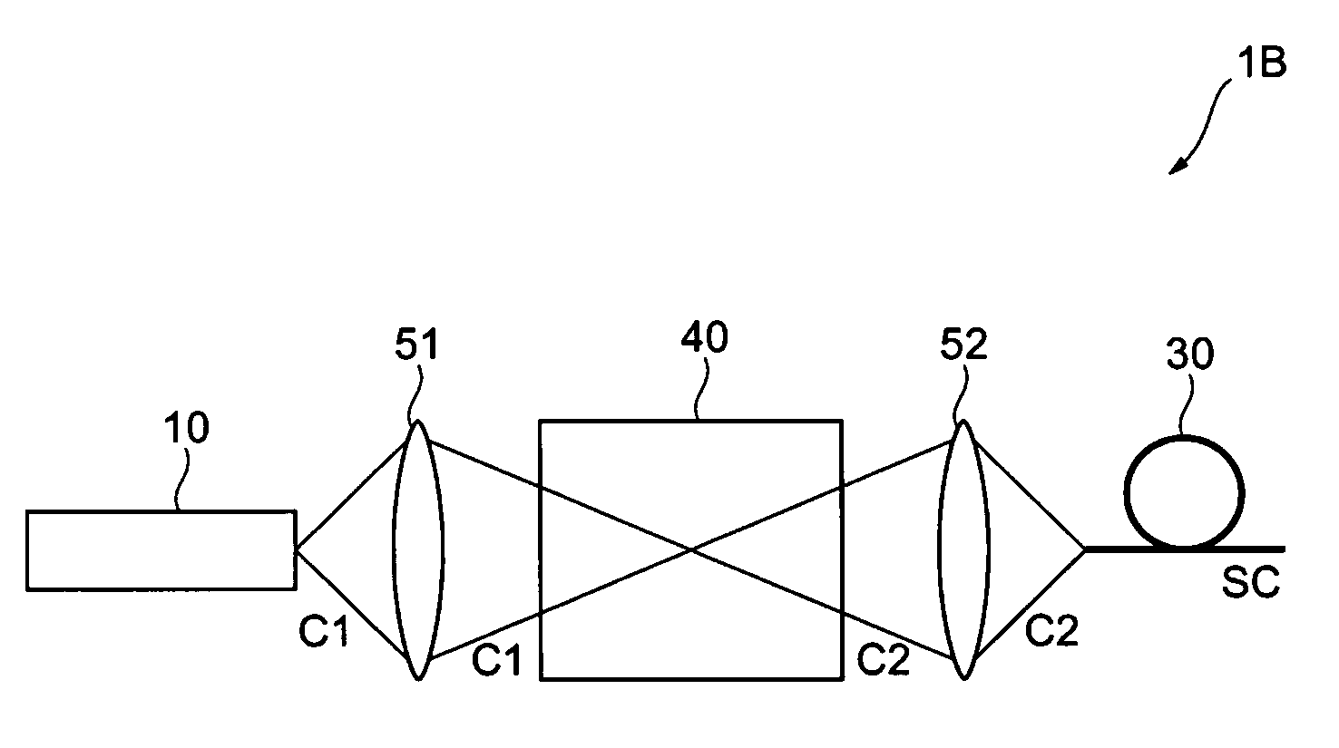
[0025]FIG. 3 schematically illustrates a broadband light source device 1B according to a second embodiment of the present invention. The broadband light source device 1B includes a DPSSL light source 10, an optical fiber 30, periodically poled lithium niobate (PPLN) 40 as a wavelength converter, a condenser lens 51, and a condenser lens 52. The PPLN 40 is a polarization-inverted crystal in which the direction of spontaneous polarization of lithium niobate (LiNbO3) is inverted alternately by 180°. The PPLN 40 receives a laser beam C1 output as seed light from the DPSSL light source 10, and generates and outputs a third harmonic laser beam C2. Since the PPLN 40 can freely design an output wavelength by periodically changing the invertible polarization structure, the PPLN 40 is capable of performing wavelength conversion at high efficiency over a broad wavelength range. Thus, the PPLN 40 can readily generate the third harmonic laser beam C2 of the laser beam C1.

[0026]The condenser lens...


PUM

PropertyMeasurementUnit
wavelength rangeaaaaaaaaaa
center wavelengthaaaaaaaaaa

Abstract

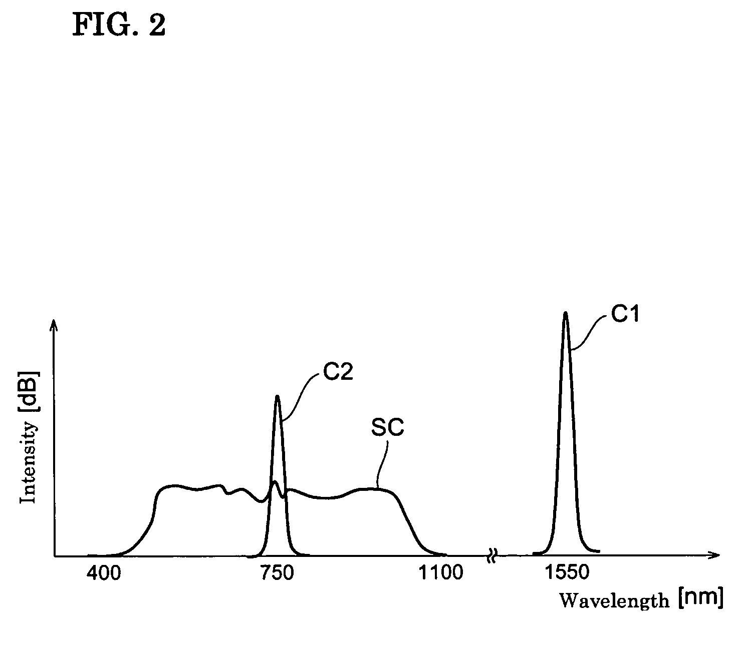
A broadband light source device that can generate supercontinuum light in a visible range and having a spectrum with a stable shape and high intensity is provided. The broadband light source device includes a diode-pumped solid-state laser light source that outputs seed light in response to being excited by a laser beam output from a semiconductor laser light source; a wavelength converter that receives the seed light to generate wavelength-converted light having a wavelength different from that of the seed light, and outputs the wavelength-converted light; and a nonlinear medium that receives the wavelength-converted light to generate supercontinuum light having a bandwidth of 100 nm or greater included in a wave band of 400 nm to 700 nm inclusive, and outputs the supercontinuum light.

Description

BACKGROUND OF THE INVENTION[0001]1. Field of the Invention[0002]The present invention relates to broadband light source devices.[0003]2. Description of the Related Art[0004]Supercontinuum light (SC light) is a type of broadband light that has a high-output, broad-band, and flat spectrum. For this reason, SC light is expected to be used in various fields of application, such as for light measurement and near-infrared spectroscopy. In particular, SC light in a visible range of 400 nm to 700 nm is much researched for its application to displays.[0005]Page 14 of the document “FemtoFiber Lasers” in TOPTICA Photonics AG's Internet website (URL: http: / / wwwtoptica.com / products / itemla_yer / 97 / BR-41003E-FFS-2006-12.pdf, searched on Apr. 11, 2007) describes a broadband light source device FFS.SYS-SHG-PCF. In this broadband light source device, an erbium-doped fiber laser is used as a seed light source, and an output laser beam is guided to a photonic crystal fiber (PCF) where a nonlinear optica...

Claims


Application Information

Patent Timeline
Patent Type & Authority Patents(United States)
IPC IPC(8): G02F1/35G02B6/00G02F2/02
CPCH01S3/06795G02F1/3558G02F1/37G02F2001/3528H01S3/0092H01S3/06741G02F2001/354G02F1/3528G02F1/354
Inventor OKUNO, TOSHIAKI
Owner SUMITOMO ELECTRIC IND LTD
Learn More