Network operating system with topology autodiscovery

a network operating system and topology autodiscovery technology, applied in the field of optical telecommunication networks, can solve the problems of affecting the service life of the network, and allowing fairly limited optical layer service offerings, so as to reduce the provisioning time of the servi

Active Publication Date: 2010-06-29
WSOU INVESTMENTS LLC
View PDF22 Cites 53 Cited by
  • Summary
  • Abstract
  • Description
  • Claims
  • Application Information

AI Technical Summary

Benefits of technology

[0020]Advantageously, the topology autodiscovery system of the invention uses a down-to-up approach and operates at the optical modules granularity; the lower layer managed objects report their presence, type and connectivity to the immediately higher layer of management. This approach allows for important reduction of SAT and consequently provides new revenue opportunities for the network providers, such as:
[0021]a) All planned or unplanned additions to the network are auto-propagated to the corresponding storage devices so as to be available to all entities that need the information. This includes physical discovery of the nodes, network elements, cards, physical fiber links. This feature reduces importantly the installation time for the equipment supporting a new service.
[0022]b) As a result of the knowledge of the current topology, the network operating system allows routing / switching of a connection along the best route for the respective CoS at a touch of a button, substantially reducing the service activation time bottleneck.
[0023]c) Still further, it allows reduction of the network engineering time and the probability of installation errors. Thus, the modular architecture of the cards, shelves and racks together with use of hierarchical levels of management and control enable automatic recognition of the topology units at each level. This in turn allows on-line verification of hardware legality, using templates for all topology units. The templates specify legal configurations that are made up of an ordered list of physical entities such as modules, card types, card / slot pairs and shelf types, and interconnections between the entities, i.e., card-to-card, shelf to shelf.
[0025]Knowledge of the current network topology also enables important reduction of the provisioning time for a service. Thus, the network operating system is provided with resource utilization capabilities, which indicate when to expand the network, and the infrastructure needed for the expansion, so that the infrastructure can be deployed by the time it is effectively required. The new resources are readily discovered and taken into account.

Problems solved by technology

Due to increased competition and eroding revenue margins, service providers are demanding better yields from their network infrastructure.
These demands have exposed a number of weaknesses with respect to the current optical networks and their mode of operation.
This network architecture allows fairly limited optical layer service offerings.
In addition, a point-to-point architecture is very difficult to scale.
Thus, the nodes complexity grows with the number of the channels, such that provisioning and engineering operations become more complex, involving extensive design, simulation, engineering and testing, which activities increase the service activation time (SAT).
This large service activation time leads to loss of revenue from a number of perspectives.
First, losing contracts due to turn-up time has driven direct loss of sales.
Naturally, once this infrastructure is in place, these traditional customers become competitors, providing services of their own.
Another disadvantage of the current network architecture is the lack of flexibility.
Thus, a point-to-point architecture does not have the ability to turn up / down bandwidth rapidly, or / and to provide bandwidth optimized for the data layer needs, even if the equipment for the new service is in place.
However, the growth of nodal complexity discussed above results in increased network management complexity.
If a service requires access to multiple network providers' infrastructures, further complications arise when different platforms need to communicate with each other.
Still another drawback of the current network management systems is the inability to maintain an accurate inventory of the network equipment.
However, such conventional inventory systems have a number of drawbacks.
These systems do not accommodate variants reflecting changes in the operation of a certain device after the equipment has been coded into the inventory, and especially if the equipment is assigned for service.
As a result, the point-to-point architecture offers a very limited range of services and does not allow for reducing the service activation time (SAT) for this limited range of services.
On the contrary, as the network scales-up, the SAT (and the cost) becomes increasingly unacceptable.

Method used


Image

  • Network operating system with topology autodiscovery
  • Network operating system with topology autodiscovery
  • Network operating system with topology autodiscovery

Examples


Embodiment Construction

Definitions

[0036]The term “agile optical network”, (also referred to as ‘photonic network’, ‘all optical network’, ‘automatically switched optical network ASON’, or ‘wavelength switched network’) refers to a network where an end-to-end connection is established along a trail, the traffic being automatically switched at all or some intermediate nodes in optical format. The nodes of an agile optical network could be optical add / drop multiplexing (OADM) nodes that provide add, drop and optical passthrough, or could be optical cross-connect nodes that provide add, drop and optical switching of the passthrough traffic.

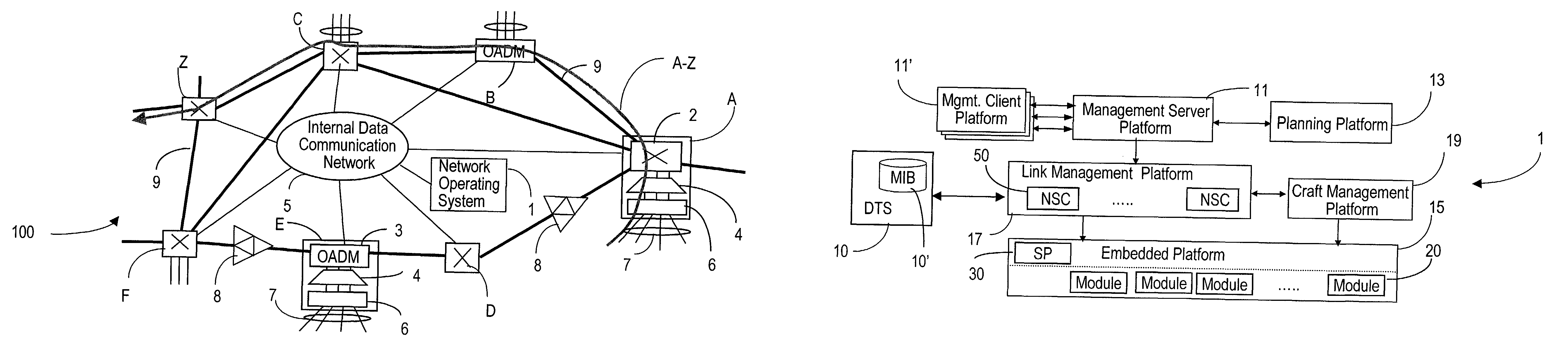
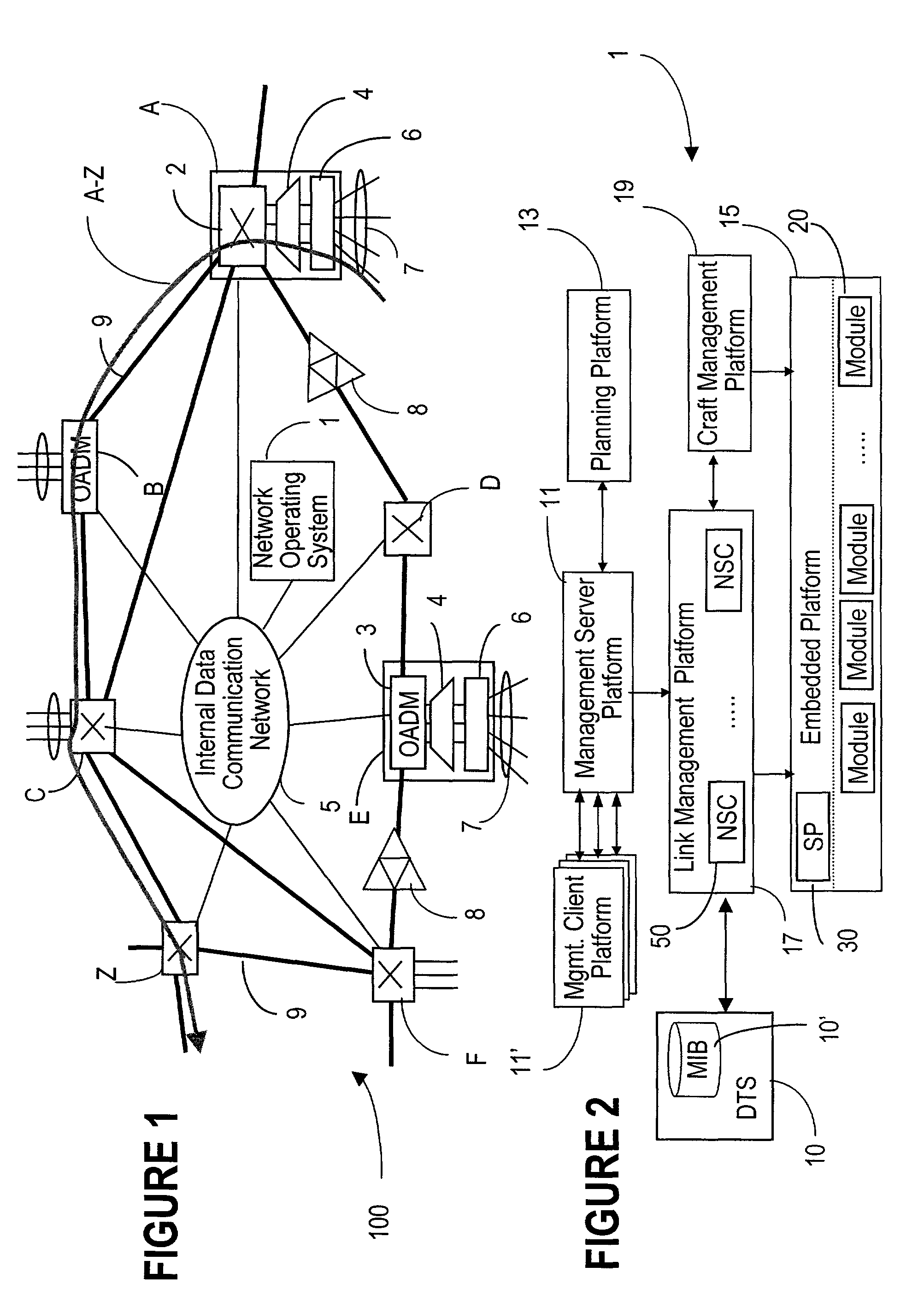
[0037]FIG. 1 illustrates an example of an agile optical network 100.

[0038]In the example of FIG. 1, network 100 comprises nodes A, B, C, Z, D, E, F, which are also called flexibility sites, connected by bidirectional fiber links 9. Optical switching nodes, such as node A, C, Z, F, D, comprise an optical switch 2 that provides optical switching of the passthrough traffic and...


PUM


Abstract

The network operating system includes an embedded platform for controlling operation of an agile optical network at the physical layer level. At the module embedded level, each module (card-pack) is provided with an embedded controller EC that monitors and control operation of the optical modules. At the next level, each shelf is provided with a shelf processor SP that monitors and control operation of the ECs over a backplane network. All optical modules are connected over an optical trace channel to send / receive trace messages that can then be used to determine network connectivity. At the next, link management level, a network services controller NSC controls the SPs in a negotiated span of control, over a link network. The control is address-based; each NSC receives ranges of addresses for the entities in its control, and distributes these addresses to the SPs, which in turn distribute addresses to the ECs in their control. One of the SPs operates as a router on the link network to relay signaling and control to all entities based on their address. Each NSC constructs, from queried information, a network topology fragment for the embedded elements under its control. A distributed topology system (DTS) shares this topology information with neighboring NSC's to build a complete network view, which can be used by all interested network applications.

Description

PRIORITY PATENT APPLICATION[0001]Provisional Patent Application “Architecture for Optical Network Manager” (Emery et al.), Ser. No. 60 / 298,008 filed on Jun. 13, 2001.FIELD OF THE INVENTION[0002]The invention resides in the field of optical telecommunication networks, and is directed in particular to providing an agile optical network with a topology autodiscovery system.BACKGROUND OF THE INVENTION[0003]Due to increased competition and eroding revenue margins, service providers are demanding better yields from their network infrastructure. In response to this demand, the next generation of transport networks must provide mechanisms for creating a number of different classes of service (CoS), while ensuring that the cost of each service is proportional to the revenue it generates. Thus, bandwidth-on-demand for event driven traffic, or creation of bandwidth brokering services are just a few of the new optical layer services that can be created. Attributes such as protection level, late...

Claims


Application Information

Patent Timeline
Patent Type & Authority Patents(United States)
IPC IPC(8): H04B10/00H04L12/24H04L29/12H04Q11/00
CPCH04J14/0227H04J14/0278H04L29/12009H04L29/12207H04L41/12H04L61/20H04J14/0228H04J14/0267H04J14/0275H04J14/0241H04Q11/0062H04Q2011/0069H04Q2011/0079H04Q2011/0088H04L61/50H04L61/00
Inventor EMERY, JEFFREY KENNETHFORTIN, GUY CLAUDEMESSERSCHMIDT, MARKUSBEER, PAUL EDWARDCRAIG, ROBERT GEORGE ALEXANDERLIM, HOCK GINDUAN, YOUXUN
Owner WSOU INVESTMENTS LLC
Why Eureka
Try Eureka