Band reject filters

a filter and band pass technology, applied in piezoelectric/electrostrictive/magnetostrictive devices, amplifiers with coupling networks, semiconductor devices/discharge tubes, etc., can solve the problems of band pass filters produced using saw resonators that have relatively high insertion losses, and typically occur losses, etc., to achieve low cost, low loss, and withstand very high rf power

Inactive Publication Date: 2010-08-17
APPLE INC
View PDF18 Cites 25 Cited by
  • Summary
  • Abstract
  • Description
  • Claims
  • Application Information

AI Technical Summary

Benefits of technology

[0015]Embodiments of the present invention allow low cost technologies such as SAW or FBAR (thin Film Bulk Acoustic Resonators) to be used to design very low loss filters which can withstand very high RF powers. These filters may achieve sufficiently low loss to be used on the front end of a network element such as a BTS (Base Transceiver Station) in a communication system, an area which tended to be reserved exclusively to very expensive cavity or waveguide filters.
[0016]Distributed filter approaches as disclosed herein also allow a filter designer to generate a desired response using only series or only shunt resonators. The resonators need not be restricted to a single die. Phase shift elements such as impedance inverters enable high levels of rejection to be achieved and also improve the pass band response.

Problems solved by technology

Furthermore, since surface acoustic waves travel across the substrate 100000 times more slowly than the speed of electromagnetic waves, such devices are generally compact and implemented on a single die.
These types of devices have found many uses, but suffer from two significant disadvantages which prevent their use in some applications.
Firstly, band pass filters produced using SAW resonators typically have relatively high insertion losses typically of a minimum of 1 or 2 dB.
The losses typically occur as a result of visco-elastic attenuations and / or mode conversions from SAW to bulk acoustic waves when the electrical energy is converted to acoustic energy and travels around the SAW filter cavity.
Secondly, the power handling capability of SAW filters is limited.
Thus, for example, at the present 1800, 1900 and 2100 MHz mobile communication bands, such filters are barely able to withstand the typical transmit powers of 500 mW to 1 W for the typical life of a handset.
Furthermore, acousto-electric migration is no longer as significant an issue and hence the device is able to handle much more power and is primarily only limited by arcing across the IDT's.
Despite the tremendous potential of SAW notch and band reject filters, relatively little work has been done on them to date.
Although filters of this type exhibit very low losses and high power handling capabilities, the design approach lacks flexibility where complex filter responses are desired.
Furthermore, to minimize loss in the pass band it is necessary to minimize the capacitance of the shunt resonator and maximize the capacitance of the series resonator, which introduce constraints on the resonator design.

Method used


Image

  • Band reject filters
  • Band reject filters
  • Band reject filters

Examples


Embodiment Construction

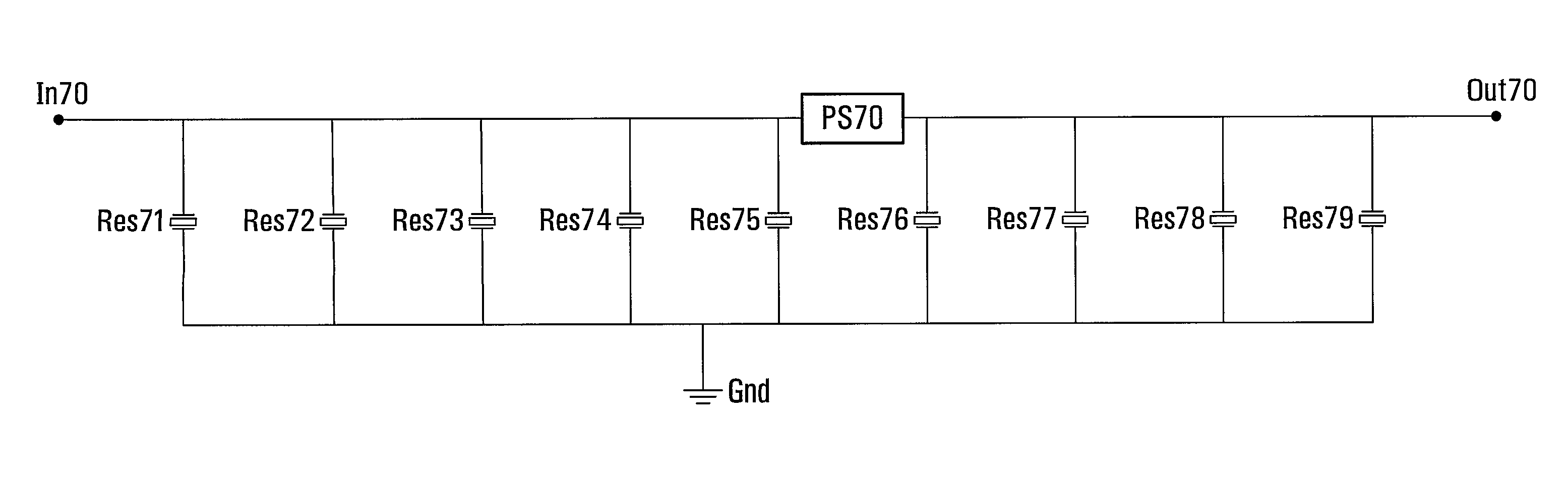
[0050]High frequency RF and microwave designs often use distributed elements. Band reject filter design can be made more versatile, with improved performance, by leveraging impedance inverters between adjacent resonators. One of the simplest forms of an impedance inverter is simply a transmission line with approximately 90° of phase shift at the desired frequency of operation. Impedance inverters can also be designed as discrete components using lumped elements at lower frequencies where the quarter-wavelength transmission line would be excessively large or where space is critical. The use of impedance inverters enables band reject filters to be created using exclusively shunt or exclusively series resonators. Furthermore, these band reject filters can be designed to utilize, as an impedance inverter, the quarter-wave transmission lines which are already present in elements such as a Quadrature coupler, Wilkinson combiner or Balun, all elements which already exist on some PA (Power ...


PUM


Abstract

Band reject filters are disclosed. A band reject filter includes a first acoustic resonator and a second acoustic resonator, each of which has either shunt resonators adapted to resonate substantially at respective resonance frequencies defining a rejection frequency band or series resonators adapted to anti-resonate substantially at respective anti-resonance frequencies defining the rejection frequency band. These resonators are connected through a phase shifter which imparts an impedance phase shift of approximately 45° to 135°. Exemplary applications of the band reject filters disclosed herein include implementation as an inter-stage band reject filter for a base station power amplifier for a wireless communication system, as a radio frequency band reject filter in a duplexer for a wireless communication terminal, and in a low noise amplifier input stage.

Description

CROSS-REFERENCE TO RELATED APPLICATIONS[0001]This application claims the benefit of U.S. Provisional Patent Application Ser. No. 60 / 623,049 filed on Oct. 29, 2004.[0002]This application also claims the benefit of, and is a National Phase Entry of, PCT Application Serial No. PCT / CA2005 / 001492 filed on Sep. 30, 2005, which in turn claims the benefit of the above provisional patent application.[0003]The entire contents of these related patent applications are incorporated in their entirety herein by reference.FIELD OF THE INVENTION[0004]This invention relates generally to filtering, and in particular to band reject filters.BACKGROUND[0005]Surface acoustic wave (SAW) devices have been studied and gradually commercialised since the mid 1960s. Such devices typically have electrodes in the form of interlocked “fingers” (so-called inter-digital electrodes) formed on a piezoelectric substrate. When high frequency signals are applied to the input electrodes, mechanical vibrations in the form ...

Claims


Application Information

Patent Timeline
Patent Type & Authority Patents(United States)
IPC IPC(8): H03H9/54H03H9/64H03H9/70
CPCH03H9/542H03H9/547H03H9/6409H03F3/602H03H9/74H03F3/60H03F3/191H03H9/706
Inventor BEAUDIN, STEVEJIAN, CHUN-YUNSYCHALEUN, SOMSACK
Owner APPLE INC
Why Eureka
Try Eureka