Ion transport device and modes of operation thereof

a mass spectrometer and ion transport technology, applied in the direction of diaphragms, electrolysis, particle separator tubes, etc., can solve the problems of significant adverse effects on the overall sensitivity of instruments, limited effectiveness of such devices, and high losses of ion transport through low vacuum regions, so as to improve the oscillatory field penetration, reduce mass discrimination effects, and optimize the transmission of certain ion species

Active Publication Date: 2010-08-24
THERMO FINNIGAN
View PDF3 Cites 50 Cited by
  • Summary
  • Abstract
  • Description
  • Claims
  • Application Information

AI Technical Summary

Benefits of technology

[0008]In either embodiment, streaming of clusters, neutrals and undesolvated droplets to the downstream, lower-pressure regions of the mass spectrometer may be reduced by one or a combination of techniques, including laterally and / or angularly offsetting the capillary with respect to the ion transport device entrance and laterally offsetting electrode apertures relative to apertures of adjacent electrodes to block a line-of-sight path.

Problems solved by technology

A fundamental challenge faced by designers of mass spectrometers is the efficient transport of ions from the ion source to the mass analyzer, particularly through atmospheric or low vacuum regions where ion motion is substantially influenced by interaction with background gas molecules.
While electrostatic optics are commonly employed in these regions of commercially available mass spectrometer instruments for ion focusing, it is known that the effectiveness of such devices is limited due to the large numbers of collisions experienced by the ions.
Consequently, ion transport losses through the low vacuum regions tend to be high, which has a significant adverse impact on the instrument's overall sensitivity.
While the ion funnel device has been used successfully in research environments, its implementation in commercial mass spectrometer instruments may be hindered by issues of cost and manufacturability.
This design results in a high part count and elevated manufacturing cost and complexity.
Furthermore, the use of a large number of ring electrodes creates a very high capacitive load, which requires a high-power amplifier to drive the circuit.

Method used


Image

  • Ion transport device and modes of operation thereof
  • Ion transport device and modes of operation thereof
  • Ion transport device and modes of operation thereof

Examples


first embodiment

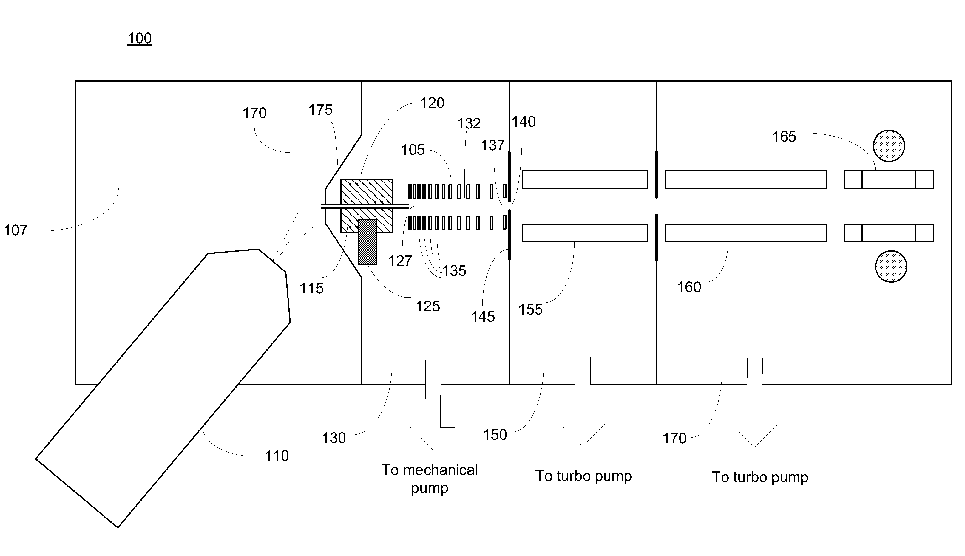
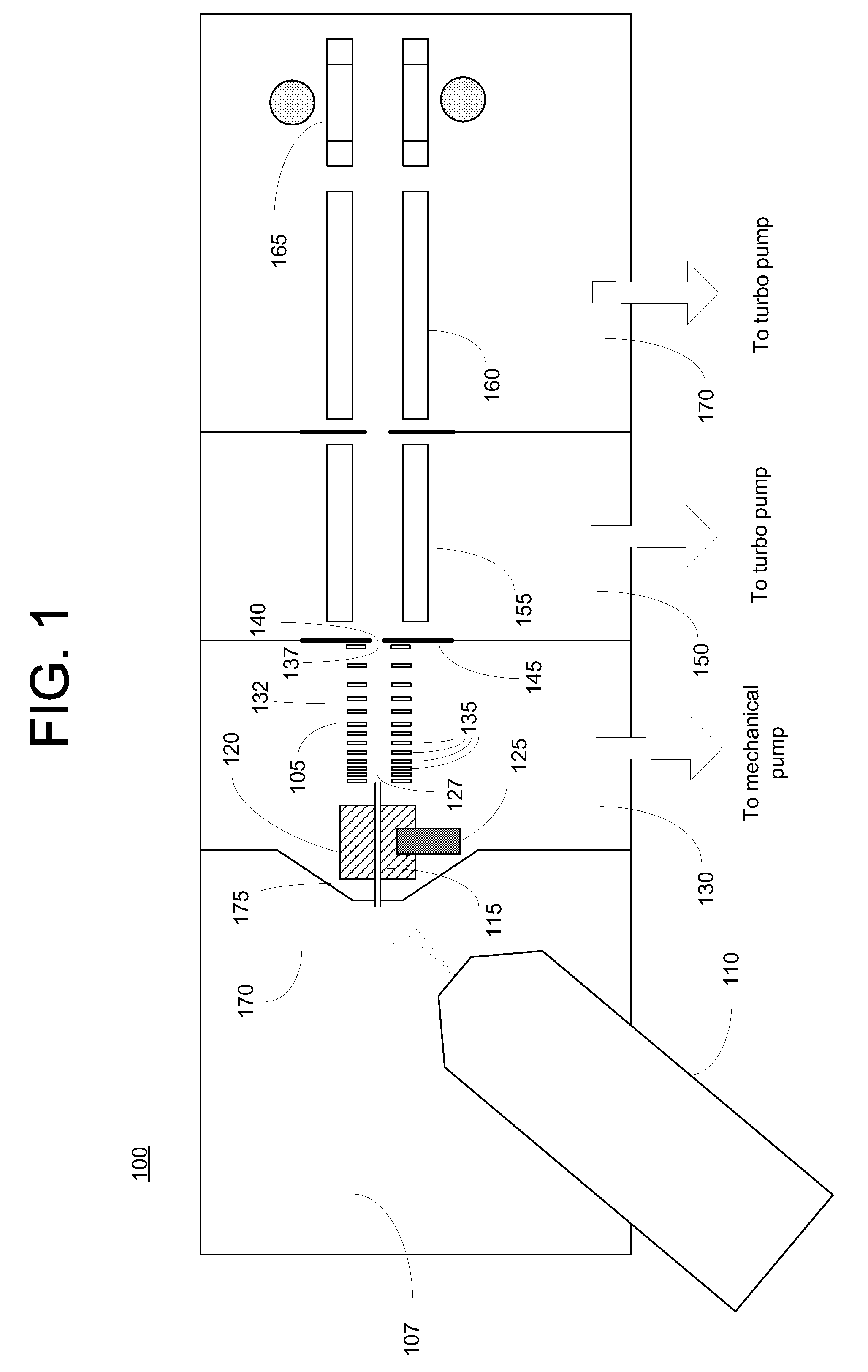
[0020]FIG. 1 is a schematic depiction of a mass spectrometer 100 incorporating an ion transport device 105 constructed in accordance with the invention. Analyte ions may be formed by electrospraying a sample solution into an ionization chamber 107 via an electrospray probe 110. For an ion source that utilizes the electrospray technique, ionization chamber 107 will generally be maintained at or near atmospheric pressure. The analyte ions, together with background gas and partially desolvated droplets, flow into the inlet end of a conventional ion transfer tube 115 (e.g., a narrow-bore capillary tube) and traverse the length of the tube under the influence of a pressure gradient. In order to increase ion throughput from ionization chamber 107, multiple ion flow channels may be provided by substituting multiple capillaries or a divided flow path ion transfer tube for the single channel ion transfer tube depicted herein. Analyte ion transfer tube 115 is preferably held in good thermal c...

second embodiment

[0030]FIG. 5 depicts an ion transport device 500 constructed in accordance with the invention. In contrast to the FIG. 2 embodiment, electrodes 505, each of which is adapted with an identically sized aperture 507, are regularly spaced along the longitudinal axis. The electrodes 505 collectively define an ion channel 510. To generate the tapered radial field that promotes a high ion acceptance efficiency at device entrance 512 and tight focusing of the ion beam at device exit 515, the amplitude of oscillatory voltages applied to electrodes 505 increase in the direction of ion travel, such that each electrode 505 receives an oscillatory voltage of greater amplitude relative to electrodes in the upstream direction. This increase in oscillatory voltage amplitude is represented by the graph depicted in FIG. 5. The desired oscillatory voltages may be delivered through a set of attenuator circuits 520 coupled to oscillatory voltage source 525. In one implementation of ion transport device ...


PUM

PropertyMeasurementUnit
pressureaaaaaaaaaa
pressureaaaaaaaaaa
pressureaaaaaaaaaa

Abstract

A device for transporting and focusing ions in a low vacuum or atmospheric-pressure region of a mass spectrometer is constructed from a plurality of longitudinally spaced apart electrodes to which oscillatory (e.g., radio-frequency) voltages are applied. In order to create a tapered field that focuses ions to a narrow beam near the device exit, the inter-electrode spacing or the oscillatory voltage amplitude is increased in the direction of ion travel.

Description

CROSS-REFERENCE TO RELATED APPLICATIONS[0001]This application is a continuation-in-part and claims the priority benefit under 35 U.S.C. §120 of U.S. patent application Ser. No. 11 / 764,100 by Senko et al., entitled “Ion Transport Device” and filed Jun. 15, 2007, now U.S. Pat. No. 7,514,673 and further claims the priority benefit under 35 U.S.C. §119 of U.S. Provisional Patent Application Ser. No. 61 / 024,868 by Splendore et al., entitled “Ion Transport Device and Mode of Operation Therefor” and filed Jan. 30, 2008. The disclosures of the foregoing patent applications are incorporated herein by reference.FIELD OF THE INVENTION[0002]The present invention relates generally to ion optics for mass spectrometers, and more particularly to a device for confining and focusing ions in a low vacuum region.BACKGROUND OF THE INVENTION[0003]A fundamental challenge faced by designers of mass spectrometers is the efficient transport of ions from the ion source to the mass analyzer, particularly throu...

Claims


Application Information

Patent Timeline
Patent Type & Authority Patents(United States)
IPC IPC(8): H01J3/14B01D59/44C25B9/17
CPCH01J3/14H01J49/065H01J49/066
Inventor SENKO, MICHAEL W.KOVTOUN, VIATCHESLAV V.ATHERTON, PAUL R.DUNYACH, JEAN JACQUESWOUTERS, ELOY R.SPLENDORE, MAURIZIOSIEBERT, WILLIAM
Owner THERMO FINNIGAN
Why Eureka
Try Eureka