Eureka AIR delivers breakthrough ideas for toughest innovation challenges, trusted by R&D personnel around the world.

Charged particle beam system and method for evacuation of the system

a particle beam and beam system technology, applied in the direction of positive displacement liquid engines, instruments, etc., can solve the problems of shortening the life of non-evaporable getters and taking a long time to do, and achieve the effect of short evacuation time and high vacuum

Inactive Publication Date: 2010-08-24
HITACHI HIGH-TECH CORP
View PDF9 Cites 17 Cited by
  • Summary
  • Abstract
  • Description
  • Claims
  • Application Information

AI Technical Summary

Benefits of technology

[0010]Therefore, the object of the present invention is to provide a charged particle beam system that is capable of performing evacuation of the charged particle source chamber having the non-evaporable getter pump in a short time and maintaining a high degree of vacuum for a long time, and a sequence of the evacuation for the charged particle beam system.
[0022]According to the present invention, the charged particle beam system equipped with an electron gun chamber or an ion gun chamber making combined use of the non-evaporable getter pump which has a short evacuation time and can maintain as high a degree of vacuum as 107 to 108 Pa for long time and the main vacuum pump, and a method for evacuation therefor can be provided.

Problems solved by technology

However, the non-evaporable getter pump has an undesirable characteristic that heating during the time of activating the alloy is attended with generation of a large amount of gas.
Exhausting the gas becomes a cause to present two problems: a problem that it takes a long time to do this exhaustion; a problem that exhaustion shortens a life of the non-evaporable getter pump which is used together with an ion pump.

Method used


Image

  • Charged particle beam system and method for evacuation of the system
  • Charged particle beam system and method for evacuation of the system
  • Charged particle beam system and method for evacuation of the system

Examples


first embodiment

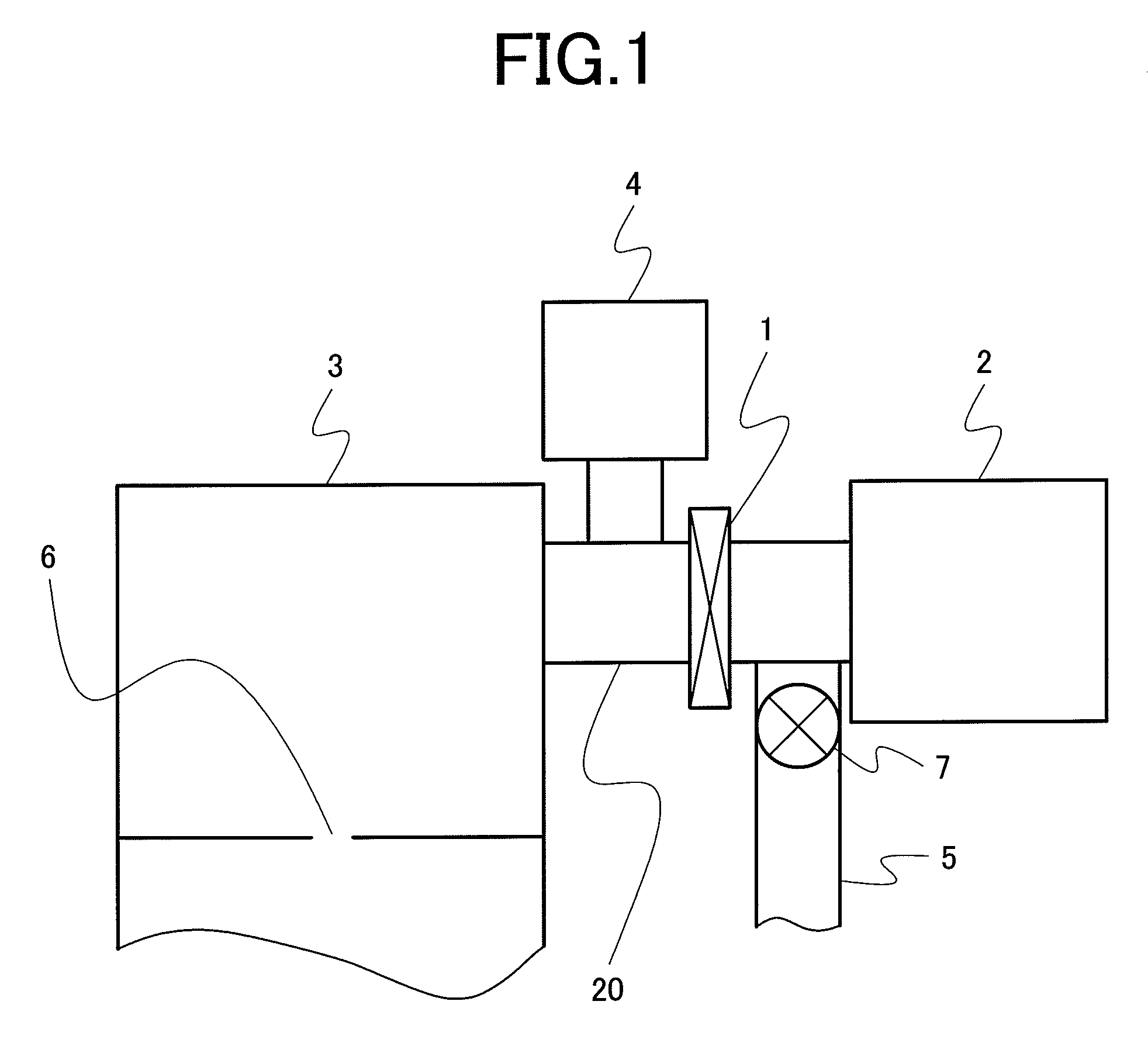
[0036]FIG. 1 shows a typical configuration example of the present invention. A vacuum vessel 3 is equipped with an electron source (not illustrated), which emits electrons downward. The emitted electron beam passes through an aperture 6, further passes through an electron optics provided under it, and falls on a sample. Further explanation is omitted here.

[0037]The vacuum vessel 3 with an electron source disposed in it connects with a main vacuum pump 4, a subsidiary vacuum pump 2, a valve 1, and a rough pumping port 5 through a vacuum pipe 20. As the main vacuum pump 4, an ion pump may be used, for example. As the subsidiary vacuum pump 2, a non-evaporable getter pump is used. At this time, the subsidiary pump 2 and a rough pumping port 5 are located on the opposite side to the vacuum vessel 3 across the valve 1, and the main pump 4 is located on the vacuum vessel 3 side across the valve 1.

[0038]That is, the means of evacuation according to this embodiment has: the vacuum vessel 3 ...

second embodiment

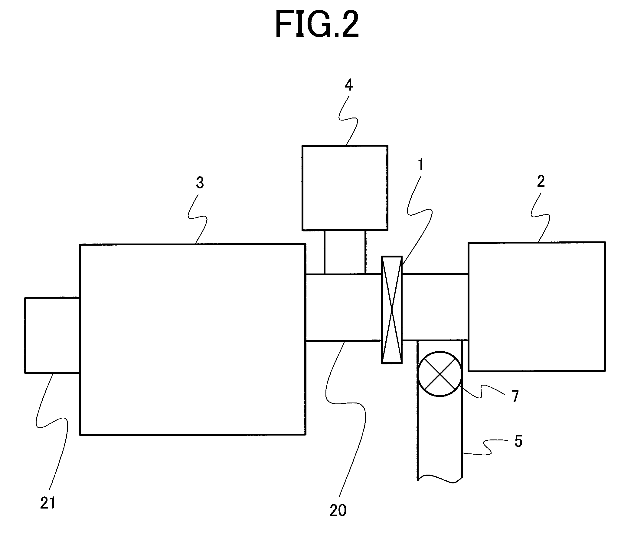
[0071]In this embodiment, a case where the evacuation configuration so far described in the First embodiment is applied to the scanning electron microscope will be explained.

[0072]FIGS. 7A and 7B show an outline configuration of the scanning electron microscope according to this embodiment. FIG. 7A show a diagram of the scanning electron microscope viewed from the above, in which there is the vacuum vessel 3 with an electron gun disposed in its most upper part, and the ion pump 4 which is a main pump is connected to the vacuum vessel 3 through the vacuum pipe. On the opposite side, the non-evaporable getter pump 2, which is the subsidiary pump 2, is provided to the vacuum pipe through the valve 1. On the subsidiary pump 2 side across the valve 1, there is the rough pumping port 5, which is connected to the vacuum pipe through the rough pumping valve 7.

[0073]As shown in FIG. 7B, under the vacuum vessel 3 with the electron gun disposed in it, there are columns having the built-in elec...

third embodiment

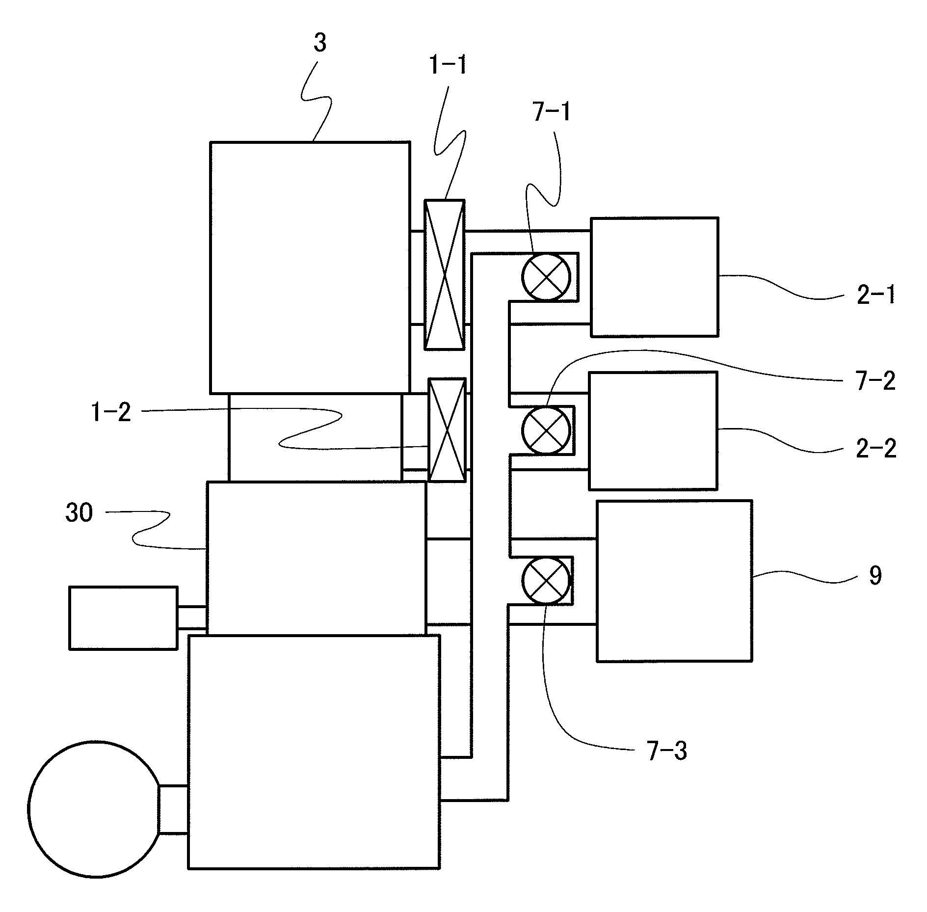
[0076]In this embodiment, a case where the present inventions is applied to the scanning electron microscope so far described in the Second embodiment in another configuration will be explained using FIG. 8.

[0077]This embodiment is an example where the ion pumps are reduced as much as possible to be only a single pump. The embodiment assumes a configuration in which the electron gun chamber 3 and the vacuum vessel immediately below it are provided only with the non-evaporable getter pumps 2-1, 2-2 (the ion pumps were removed), and only a third vacuum vessel 30 is evacuated by the ion pump 9. In this case, there are effects that the ion pumps are cut, and miniaturization and lightening of the scanning microscope are attained.

[0078]The method for evacuation is almost equivalent to that of the Second embodiment. The following can be attained: In activating the non-evaporable getter pumps 2-1, 2-2, valves 1-1, 1-2 are shut and rough pumping valves 7-1, 7-2 are opened, so that a large am...


PUM


Abstract

The present invention provides a charged particle beam system which can perform evacuation on an electron gun chamber or an ion-gun chamber having a non-evaporable getter pump in a short time and can maintain the ultra-high vacuum for a long time, and a technology of evacuation therefor. Provided is a charged particle beam system equipped with a charged particle optics which makes the charged particle beam emitted from a charged particle source incident on a sample and means of evacuation for evacuating the charged particle optics, characterized in that the evaporation means has: a vacuum vessel with a charged particle source disposed in the vessel; a non-evaporable getter pump which connects with the vacuum vessel through a vacuum pipe and evacuates the interior of the vacuum vessel as a subsidiary vacuum pump; a valve interposed in the vacuum pipe connecting between the vacuum vessel and the non-evaporable getter pump; a rough pumping port which is provided closer to the non-evaporable getter pump than the valve and performs rough pumping; an open and shut valve for opening and shutting the rough pumping port; and a main vacuum pump which is provided closer to the vacuum vessel than the valve and evacuates the interior of the vacuum vessel.

Description

CLAIM OF PRIORITY[0001]The present invention claims priority from Japanese application JP 2007-161260, filed on Jun. 19, 2007, the content of which is hereby incorporated by reference on to this application.BACKGROUND OF THE INVENTION[0002]The present invention relates to a charged particle beam system, such as an electron microscope, an electron beam lithography apparatus, and a focused ion beam system, more specifically, to an extremely high degree of vacuum technology of an electron gun or ion gun part.[0003]Conventional scanning electron microscope (SEM) and electron beam writer (EB) each accelerate an electron beam emitted from an electron gun constructed with a field emission type or thermal field emission type electron source, convert it into a narrow electron beam with electron lenses, scan it on a sample as a primary electron beam using a scanning deflector, and perform (in the case of the SEM) detecting secondary electrons or reflected electrons obtainable from the above p...

Claims


Application Information

Patent Timeline
Patent Type & Authority Patents(United States)
IPC IPC(8): F04B37/02H01J37/301F04B37/14
CPCH01J37/18H01J37/28H01J37/3056H01J2237/182H01J2237/1825
Inventor KATAGIRI, SOUICHIOHSHIMA, TAKASHI
Owner HITACHI HIGH-TECH CORP
Why Eureka
Eureka Blog
Learn More