In-situ method to reduce particle contamination in a vacuum plasma processing tool

a plasma processing tool and vacuum technology, applied in the direction of cleaning machines, carpet cleaners, applications, etc., can solve the problems of poor handling, outdated tool design, and severe impairment of the functionality of the device produced by such procedures

Inactive Publication Date: 2010-09-21
WESTERN DIGITAL TECH INC
View PDF17 Cites 9 Cited by
  • Summary
  • Abstract
  • Description
  • Claims
  • Application Information

AI Technical Summary

Benefits of technology

[0011]Briefly, one embodiment of the present invention includes employing an in-situ particle decontamination technique that allows for such decontamination using existing plasma processing equipment without breaking vacuum. This, thereby, supplements to the need for another device for performing decontamination and enables in-situ decontamination prior to functional plasma processing without breaking vacuum. An embodiment of the present invention is a method to decontaminate using an RF diode configuration. Particle decontamination is performed in the presence of an RF plasma, with a maximized substrate “self bias” voltage. The negatively charged particles are propelled by the coulomb electrostatic forces from similarly charged substrate. The particles are further driven away by the plasma potential gradient near plasma-substrate interface.

Problems solved by technology

However, the functionality of devices produced by such procedures can be severely impaired if foreign substances, in the form of micro particulate, are contaminating the surface of the wafer.
Such contamination usually comes from poor handling and outdated tool design and inadequate manufacturing controls.
In applications, such as magnetic disk recording drives, utilizing microelectromagnetic devices, the presence of undesirable particles on the wafer surface thereof is similarly detrimental in that, for example, if a particle is in line with a critical dimension of a device feature in the recording head (a device used to read and / or write to the magnetic recording disk), the disk drive is essentially rendered inoperational.
That is, the head devices on the contaminated wafer are essentially wasted.
All prior art methods, since they are ex-situ standing-alone non-integrated methodologies, are “upstream” and ineffective.
Multiplication of particle contamination introduces particles into the critical dimension of heads of disk drives essentially reduces yield and raises manufacturing unit costs.
For example, electrostatic decontamination devices are utilized but no method or apparatus offers decontamination to take place directly within the vacuum tool or in-situ.
However, this technique, firstly, requires a separate device, i.e. the electrostatic decontamination device and secondly gas flow is required to blow particles.
The disadvantage of such ex-situ particle reduction devices is that the method is useless for contamination from an internal source such as a malfunctioning vacuum deposition tool (e.g. during wafer mechanical transferring between process modules).
That is, it is vacuum incompatible.
The state-of-the-art recording head processing technology, and microelectronic processing, in general, calls for multi-layer and multi-module processing cluster equipment with integrated complex mechanical systems, which increase exposure to in-situ contamination due to increased frequency of wafer in situ mechanical handling.
Such limitation of prior art ex-situ particle decontamination devices is therefore inadequate in reducing such contamination related yield and reliability problems.
The only viable solution to such problem is increased tooling, renewal and increase in maintenance frequency resulting in increased productivity costs and cycle time.
In summary, in prior art techniques, a particle ionizing device is employed for decontamination of the surface of the wafer, however, this is a stand-alone device specifically designed for particle contamination and requiring added steps for this purpose, and is only good for decontamination of upstream ex-situ sources.

Method used


Image

  • In-situ method to reduce particle contamination in a vacuum plasma processing tool
  • In-situ method to reduce particle contamination in a vacuum plasma processing tool
  • In-situ method to reduce particle contamination in a vacuum plasma processing tool

Examples


Embodiment Construction

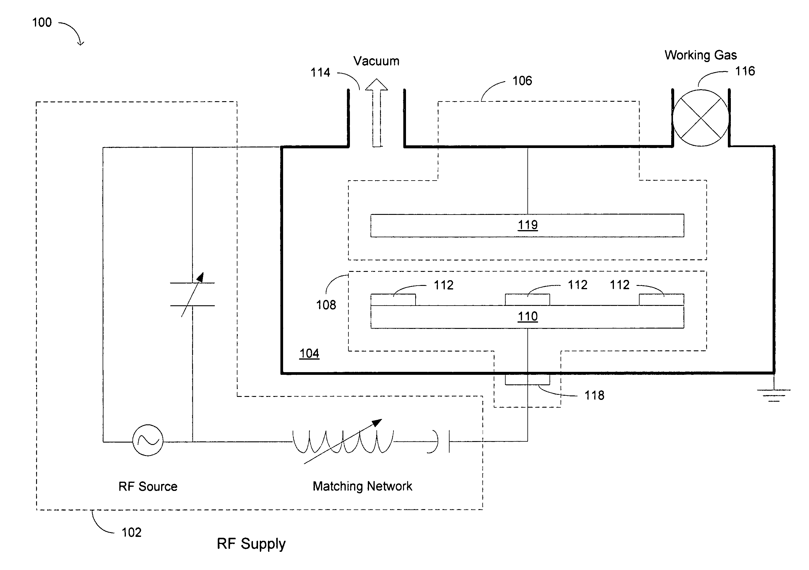
[0021]The embodiments of the present invention include a methodology to decontaminate particles in-situ without interrupting vacuum processing and can therefore be used to safeguard against yield detractors resulting from internal particle source inside of a vacuum tool or chamber. The methodology takes advantage of particle-substrate electrostatic Coulomb interaction as well as plasma glow characteristics. The principle is taught using examples from vacuum processing equipment with RF capabilities such as an RF diode sputtering system. Substrate is RF powered such that the self bias voltage is maximized. The charged particles are repelled by the Coulomb electro-static force and plasma potential gradient. However, this principle can be applied to other relevant vacuum technologies.

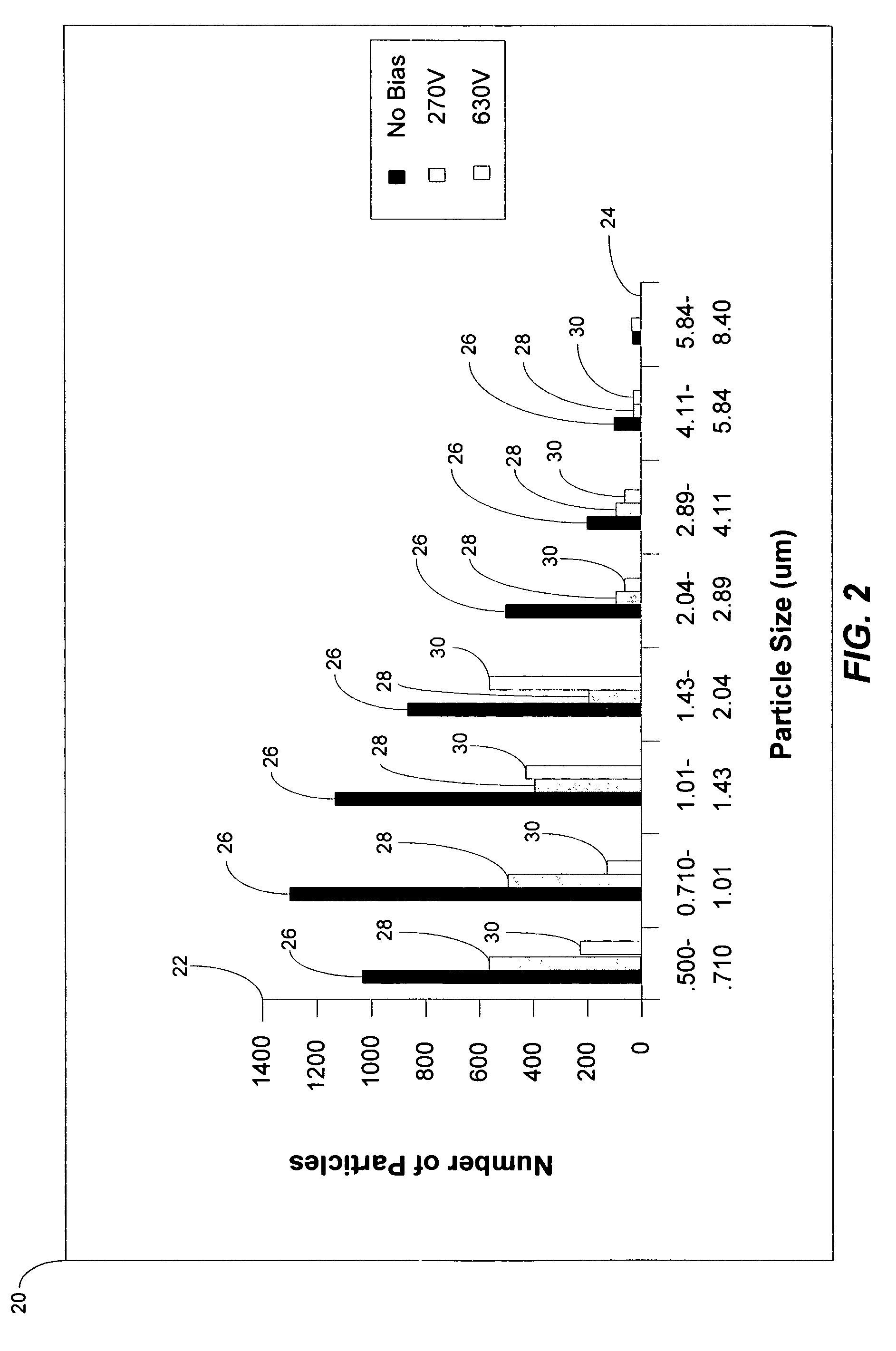
[0022]Referring now to FIG. 2, a graph 20 is shown of an example of a relationship between the particle vs. particle size when methods and apparatus of the present invention are employed. Ar is used as a w...


PUM

PropertyMeasurementUnit
voltageaaaaaaaaaa
pressureaaaaaaaaaa
diameteraaaaaaaaaa

Abstract

The method and apparatus of the embodiments of the present invention employ an in-situ particle decontamination technique that allows for such decontamination while a wafer is a vacuum tool or deposition chamber, thereby eliminating the need for another device for performing decontamination. This in-situ decontamination is effective for particle contamination resulting, for example, from tool resident mechanical component. Furthermore, particle decontamination is performed in the presence of plasma, having a potential for helping to maximize a “self bias” voltage, under RF conditions, and is integrated into the vacuum process.

Description

BACKGROUND OF THE INVENTION[0001]1. Field of the Invention[0002]This invention relates generally to the field of particle decontamination during manufacturing of semiconductor devices, a plurality of which are formed on a wafer, and particularly to a method and apparatus for reducing particle contamination of the wafer while the wafer is in a vacuum, in-situ.[0003]2. Description of the Prior Art[0004]Semiconductor devices are manufactured on a smaller scale due to a variety of recent applications of semiconductor, microelectronic and microelectro-mechanical devices requiring small-scale devices. Small scale device manufacturing further increases the need for wafer decontamination.[0005]During semiconductor device manufacturing, wafers are typically formed in vacuum deposition tools, such as vacuum plasma processing tools, with the wafer being loaded outside of the vacuum and then brought into the vacuum for thin film deposition and various ion etching or other processing. However, t...

Claims


Application Information

Patent Timeline
Patent Type & Authority Patents(United States)
IPC IPC(8): C25F3/30
CPCC23C14/021C23C14/564H01J37/32706H01J2237/022
Inventor FONTEJON, JR., PAUL ALEJONGAO, YUNXIAOLIU, YINSHISHI, NING
Owner WESTERN DIGITAL TECH INC
Why Eureka
Try Eureka